
User manual


Host
Computer
=
DC Power
Supply
Load
+
-
remove
jumper
+
-
Test Setup
www.ti.com
4.3.2 J10 – CTRL
This is the interface connector for the CTRL interface. Connect the 10-pin ribbon cable between this
connector and the I/O connector of the USB interface adapter.
5 Test Setup
5.1 EVM Operation
The user must connect an input power supply set between 2.3 V and 5.5 V between headers J1 and J3 in
order for the EVM to operate. The absolute maximum input voltage is 7 V.
The user can connect a load resistance between the positive and negative output voltage, J4 and J7, or
the two output voltages and GND, J4 and J6, and J7 and J9.
5.2 Software Setup To Change Negative Output Voltage
The software is not needed for testing the standard operation of the TPS65137AEVM, but if changing the
negative output voltage is necessary, the software has to be installed, and the USB interface adapter used
with a host computer.
For the newest software version, go to the TPS65137A product folder on the TI Web site
(http://focus.ti.com/docs/prod/folders/print/tps65137.html), download the software (zipped file), unpack it,
and execute the setup.exe file. This installs the newest software version on your PC. It is recommended to
remove older versions before installing the newest one.
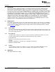
5.3 Hardware Setup
Figure 2 details the connection of the power supply, the load, and the host computer. The host computer
is just required if a voltage change on the negative rail is needed. The connection of the load is just an
example; the load(s) can also be connected between J4 and J6 and/or J7 and J9.
Figure 2. Connection of the Board and Host Computer
5.4 Software Operation
After the installation of the software, an icon with the name TPS65137 EVM appears on the desktop of the
host computer. If it does not, browse the program files in the Start menu for the software. The default
location is Program Files/Texas Instruments/TPS65137 EVM.
After connecting the USB interface adapter to the host computer, the software can be started. Most likely,
at the first startup, the system asks to update the adapter's firmware. After confirmation of this update, the
software window shown in Figure 3 appears.
6
TPS65137A Evaluation Module SLVU378–August 2010
Copyright © 2010, Texas Instruments Incorporated