
User manual


www.ti.com
Board Layout
3 Board Layout
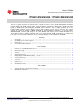
Board layout is critical for all switch mode power supplies. Figure 6, Figure 7, and Figure 8 show the board
layout for the HPA283 PCB. The switching nodes with high-frequency noise are isolated from the
noise-sensitive feedback circuitry, and careful attention has been given to the routing of high-frequency
current loops. See the data sheet for more specific layout guidelines.
Figure 6. Top Assembly Layer
Figure 7. Top Layer
7
SLVU223B– February 2008–Revised May 2011 TPS61181EVM-259 / TPS61182EVM-259
Submit Documentation Feedback
Copyright © 2008–2011, Texas Instruments Incorporated