
User manual


Setup
www.ti.com
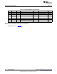
Table 1. Factory EVM Jumper Settings
Jumper Shunt Location
JP1 Installed
JP2 Installed
JP3 Installed
JP4 Installed
JP5 Installed
JP6 Installed
JP7 Installed
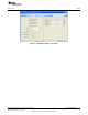
2.3.1 TPS6025x Software Operation
The software is designed to work with the entire TPS60250/1/2 family of devices. A screenshot of the
software is shown in Figure 1. Upon being opened, the software asks the user to select which particular
EVM is installed.
The top part of the software contains a link to the device datasheet as well as buttons to read and write all
the registers.
The bottom part of the software indicates that the USB-to-GPIO adaptor is installed and working properly.
It also notes the I
2
C bus speed (100 kHz).
2.3.1.1 Left Half of Software GUI - Settings
This portion of the software allows the user to enable/disable the different banks of LEDs using simple
check boxes. Open lamp detection may be enabled/disabled using the provided check box. Refer to the
TPS60250 data sheet for a description of the open lamp detection. Additionally, a pulldown box (MODE) is
available to control the aux display settings. The aux display may be grouped with main display or set for
the separate high-current (80 mA) aux display. When using the high-current setting, it is suggested that
separate LEDs are connected between the J5 (cathode connection) and J6 (anode connection)
connectors. The LEDs installed on the EVM are rated for 30-mA dc current and may be damaged at the
higher current. Selecting the shutdown option in the Aux Display pulldown menu disables all of the LEDs
and places the IC in a low-power shutdown mode. The internal registers are not changed in this mode.
Another MODE pulldown box allows selection of what switching mode is used to drive the WLEDs: auto
switch, forced 1x, or forced 1.5x. Finally, there are 3 pulldown boxes at the bottom to set the WLED
current for each of the banks.
2.3.1.2 Right Half of the GUI - Register Map
This portion of the software allows the user to change the registers on a bit level. All this functionality is
already included in the easy to use boxes and pulldowns on the left half side of the GUI.
4
TPS60250EVM-185 SLVU208B–April 2007–Revised December 2012
Submit Documentation Feedback
Copyright © 2007–2012, Texas Instruments Incorporated