
Datasheet


Table Of Contents
VDD
GND
RST
0.9V-6.5V
1
RST
2
NC
5
PWPD
3
GND
4
VDD
U1
TPS3839K33DQN
J1
J2
J3
C1
0.1 Fm
www.ti.com
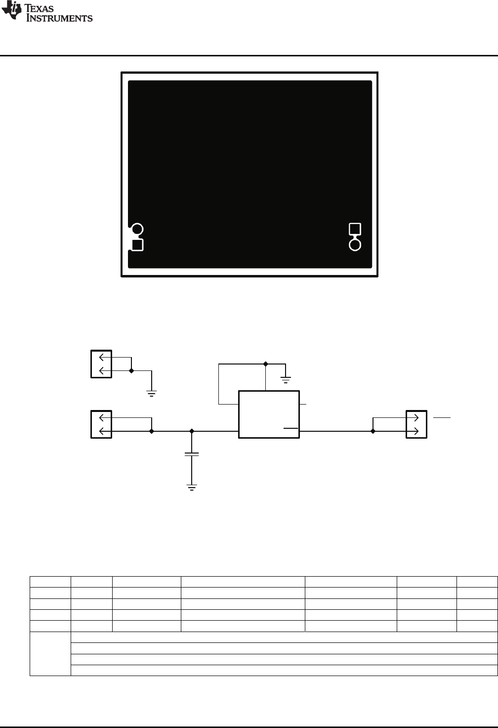
Schematic
Figure 3. Bottom Layer Routing
5 Schematic
Figure 4. TPS3839K33EVM-112 Schematic
6 Bill of Materials
Table 1. TPS3839K33EVM-112 Bill of Material
COUNT RefDes Value Description Size Part Number MFR
1 C1 0.1uF Capacitor, Ceramic Chip, 10V, X5R, ±10% 402 STD STD
3 J1-3 PEC02SAAN Header, Male 2-pin, 100mil spacing, 0.100 inch x 2 PEC02SAAN Sullins
1 U1 TPS3839K33DQN IC, Supply Voltage Supervisory Circuit, 3.3V SON TPS3839K33DQN TI
1 - PCB PCB, 1.30 In x 1.645 In x 0.062 In 1.30 In x 1.645 In x 0.062 In PWR112 Any
Notes: 1. These assemblies are ESD sensitive, ESD precautions shall be observed.
2. These assemblies must be clean and free from flux and all contaminants. Use of no clean flux is not acceptable.
3. These assemblies must comply with workmanship standards IPC-A-610 Class 2.
4. Ref designators marked with an asterisk ('**') cannot be substituted. All other components can be substituted with equivalent MFG's components.
3
SLVU758–July 2012 TPS3839K33EVM-112 Evaluation Module
Submit Documentation Feedback
Copyright © 2012, Texas Instruments Incorporated