User’s Guide April 2001 PMP PD & PS SLVU048
IMPORTANT NOTICE Texas Instruments and its subsidiaries (TI) reserve the right to make changes to their products or to discontinue any product or service without notice, and advise customers to obtain the latest version of relevant information to verify, before placing orders, that information being relied on is current and complete.
How to Use This Manual Preface How to Use This Manual This document contains the following chapters: - Chapter 1—Introduction - Chapter 2—48-V Telecom Hot Swap - Chapter 3—Schematics of the EVM and the Interface Card - Chapter 4—Layouts of the EVM and the Interface Card - Chapter 5—Setup of the EVM - Chapter 6—Test Points FCC Warning This equipment is intended for use in a laboratory test environment only.
iv
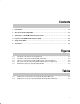
Running Title—Attribute Reference 1 Introduction . . . . . . . . . . . . . . . . . . . . . . . . . . . . . . . . . . . . . . . . . . . . . . . . . . . . . . . . . . . . . . . . . . . . . 1-1 2 48-V Telecom Hot-Swap EVM . . . . . . . . . . . . . . . . . . . . . . . . . . . . . . . . . . . . . . . . . . . . . . . . . . . . . 2-1 3 Schematics of the EVM and the Interface Card . . . . . . . . . . . . . . . . . . . . . . . . . . . . . . . . . . . . .
Running Title—Attribute Reference vi
Chapter 1 Fast development of telecommunications and networks has accelerated growth of products with hot-plug capability to ensure that systems are always on. Many hot-swap or hot-plug devices are already available in the worldwide market. However, most such devices are for low-voltage applications, whereas 48-V is a standard voltage in most communication systems.
1-2 Introduction
Chapter 2 ! With the rapid growth of internet and telecommunications in general, more and more electronic systems are required to run continuously. Therefore, redundant systems or modules may be required to prevent the crashing of systems. While redundant systems have proved feasible, they are also very costly. Further, a simple redundant system as a backup is often inadequate because any errant part in the backup can jeopardize the whole system.
2-2 48-V Telecom Hot-Swap EVM
Chapter 3 " ! " The evaluation kit includes two boards: one is the hot-swappable TPS2330EVM-184 48-V hot-swap EVM (SLVP184 board) where the TPS2330 controls voltage ramp-up and reduces inrush current during hot-plug events; the other is an interface card (SLVP155 board) that supplies power to the 48-V hot-swap board. Figures 3–1 and 3–2 show the schematic of the interface card and the schematic of the hot-swappable EVM respectively. Figure 3–1.
Because the interface card was originally designed for universal application purposes, some of the components shown in the schematic above may not be on the board when shipped with this EVM kit. Refer to the bill of materials table for a complete component list. A key is installed in the edge connector on the interface board (SLVP155) to ensure that the hot-swap board can only be inserted the right direction.
The bills of materials (BOM) for both boards are shown in Tables 3–1 and 3–2, respectively. Table 3–1. Components on the Interface Card (SLVP155), Bill of Materials Ref Des Qty Part Number C1, C2, C3 Not used C4, C6 Not used C5 1 C7, C8, C9 Mfg Size 1210 12061C104KAT2A Capacitor, ceramic, 0.1-µF, 1100-V, +X7R, 10%, Y5V Taiyo Yuden 3267 Connector, banana jack, uninsulated Pomona 50–22SN–11 Connector, 44-pin edge w/mtg tabs (for 0.
C4 and C8 on SLVP184 adjust the output turnon ramp-up rate and propagation delay time. Reducing the capacitance of C8 will increase the output ramp-up speed, and decreasing the value of C4 will reduce the output turnon delay time and increase the output ramp-up rate.
Chapter 4 # $ " ! " The following figures illustrate the placements of the components and the top-layer layouts for both the 48-V hot-swap EVM and the interface card respectively. All the components are placed on the top layers except for the 0.1-µF capacitor (C8) on SLVP184 that has now been included on the bottom layer. (The bottom layers are mainly ground planes).
Figure 4–1.
Figure 4–2.
4-4 Layouts of the EVM and the Interface Card
Chapter 5 " ! For proper operation of the EVM, one 48-V power supply, and a voltage meter or an oscilloscope are required. Refer to the setup diagram in Figure 5–1 and follow these steps for hot plug testing: 1) Verify that the power-supply voltage is set at 48 V. Make sure the supply has the capability to provide the current loads need. Turn off the supply. 2) Connect a meter or oscilloscope to monitor the voltages from Vout+ (pin 1 of J1) to Vout– (pin 2 of J1) on the SLVP184 board.
Figure 5–1. Evaluation Setup of the Hot-Swap Board EVM Power Supply 48–V, 1–A Supply – + Plug SLVP184 board into edge connector. Note key and slot loctions.
Chapter 6 % Two test points are available on the interface card (SLVP155): TP1 – VIN1 (input voltage) TP5 – GND (ground) On the 481-V hot-swap EVM, there are total 7 test points: TP1 – Gate of the IRF530N MOSFET TP2 – Input (VIN) of TPS2330 TP3 – VIN+ (EVM positive input rail, same as Vout+) TP4 – Vout+ (EVM positive output rail, same as VIN+) TP5 – Power-good output TP6 – Vout– (EVM negative output rail) TP7 – VIN– (EVM negative input rail) Test Points 6-1
6-2 Test Points