
User guide


Setup
3-2
3.1 Setup
The HPA074 EVM is designed to allow evaluation of the TPS2231 device. Test
points and slide switches are provided to facilitate various tests and configura-
tions.
3.2 Slide Switches
On the HPA074 EVM, 6 slide switches (S1 through S6) are provided to set the
logic levels on the TPS2231 logic inputs. When the handle of a switch is placed
on position 1, the respective TPS2231 input will be pulled up to the AUXIN for
S1 to S5 or Hi-Z for S6. If a switch is placed on position 0, the respective logic
input will be connected to ground (GND).
Switch Name Related Signal Initial Position
S1 STBY 1
S2 SHDN 1
S3 SYSRST 1
S4 CPPE 1
S5 CPUSB 1
S6 RCLKEN 1
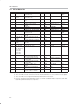
3.3 Test Points
All of the test points on the HPA074 EVM are listed in the following table.
Test Points Description
TP1, TP11, TP20 Ground (GND)
TP2 Test point for TPS2231 AUXIN pin
TP3 Test point for TPS2231 STBY pin
TP4 Test point for TPS2231 SHDN pin
TP5 Test point for TPS2231 SYSRST pin
TP6 Test point for TPS2231 OC pin
TP7 Test point for TPS2231 AUXOUT pin
TP8 Test point for U2 output pin (inverting output clock)
TP9 Test point for U4 output pin (noninverting output clock)
TP10 Test point for U3 output pin (input clock)
TP12 Test point for TPS2231 3.3VIN pin
TP13 Test point for TPS2231 3.3VOUT pin
TP14 Test point for TPS2231 PERST pin
TP15 Test point for TPS2231 CPPE pin
TP16 Test point for TPS2231 CPUSB pin
TP17 Test point for TPS2231 RCLKEN pin
TP18 Test point for TPS2231 1.5VIN pin
TP19 Test point for TPS2231 1.5VOUT pin