! "#$ # % & ' User’s Guide September 2001 Mixed Signal Products SLVU050
IMPORTANT NOTICE Texas Instruments Incorporated and its subsidiaries (TI) reserve the right to make corrections, modifications, enhancements, improvements, and other changes to its products and services at any time and to discontinue any product or service without notice. Customers should obtain the latest relevant information before placing orders and should verify that such information is current and complete.
EVM IMPORTANT NOTICE Texas Instruments (TI) provides the enclosed product(s) under the following conditions: This evaluation kit being sold by TI is intended for use for ENGINEERING DEVELOPMENT OR EVALUATION PURPOSES ONLY and is not considered by TI to be fit for commercial use.
EVM WARNINGS AND RESTRICTIONS It is important to operate this EVM within the specified input and output ranges described in the EVM User’s Guide. Exceeding the specified input range may cause unexpected operation and/or irreversible damage to the EVM. If there are questions concerning the input range, please contact a TI field representative prior to connecting the input power.
Related Documentation From Texas Instruments Preface Read This First How to Use This Manual This document contains the following chapters: - Chapter 1 – Introduction - Chapter 2 – Hardware Overview - Chapter 3 – EVM Operation - Chapter 4 – Bill of Materials - Chapter 5 – EVM Layout Related Documentation From Texas Instruments TPS2149 3.3-V LDO and Dual Switch data sheet, literature number SLVS401. TUSB2136 USB Keyboard Hub Controller data sheet, literature number SLLS442.
vi
Contents Contents 1 Introduction . . . . . . . . . . . . . . . . . . . . . . . . . . . . . . . . . . . . . . . . . . . . . . . . . . . . . . . . . . . . . . . . . . . . . 1-1 1.1 Required Hardware and Software . . . . . . . . . . . . . . . . . . . . . . . . . . . . . . . . . . . . . . . . . . . . . 1-2 2 Hardware Overview . . . . . . . . . . . . . . . . . . . . . . . . . . . . . . . . . . . . . . . . . . . . . . . . . . . . . . . . . . . . . . 2-1 3 EVM Operation . . . . . . . . . . . . . . . . . . .
viii
Chapter 1 Introduction This user’s guide describes the setup and operation of the USB keyboard/hub evaluation module (EVM). Information and instruction presented throughout this document assumes user familiarity with universal serial bus (USB) protocol and the use of common lab testing equipment. Topic 1.1 Page Required Hardware and Software . . . . . . . . . . . . . . . . . . . . . . . . . . . . . .
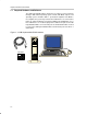
Required Hardware and Software 1.1 Required Hardware and Software The USB keyboard/hub EVM is designed for use with a personal computer running a USB-enabled operating system. The PC, with BIOS, chipsets, and operating system, should be USB 1.1 specification-compliant. If the BIOS is not compliant, the system may not boot when USB devices are connected at power up, and the EVM may not function in DOS mode.
Chapter 2 Hardware Overview The USB keyboard/hub EVM is 4-inches L × 3.5-inches W and features the TPS2149 made by Texas Instruments. The TPS2149 is a power management device that integrates an LDO and two power switches into one small package. Jumpers (0-Ω resistors) and jumper blocks provided on the EVM are installed with the factory settings. The settings are described in Table 3–2. Review all setting changes prior to powering the EVM.
2-2
Chapter 3 EVM Operation Operation of the USB keyboard/hub EVM is summarized in paragraphs 3.1 through 3.6. Topic Page 3.1 TPS2149 Setup . . . . . . . . . . . . . . . . . . . . . . . . . . . . . . . . . . . . . . . . . . . . . . . 3-2 3.2 Interfaces and USB Ports . . . . . . . . . . . . . . . . . . . . . . . . . . . . . . . . . . . . . . 3-2 3.3 Power Supplies . . . . . . . . . . . . . . . . . . . . . . . . . . . . . . . . . . . . . . . . . . . . . . 3-2 3.4 Light-Emitting Diodes (LEDs) . . . . .
TPS2149 Setup 3.1 TPS2149 Setup The USB keyboard/hub EVM is designed to allow evaluation of the TPS2149 device. Test points and 0-Ω resistors are provided to simplify the evaluation process (see Section 3.5). The EVM comes in a default configuration that requires no additional components, other than the required hardware and software identified in Section 1.1 of this user’s guide. For a complete description of the TPS2149 device, consult the TPS2149 data sheet (literature number SLVS401). 3.
Jumpers and Test Points 3.5 Jumpers and Test Points Table 3–2 describes the jumpers, J1 and J2, used to connect P3.0 and P3.1 to D6 and D7 respectively, which should only be done when P3.0/S0 and P3.1/S1 are not set to GND for VID/PID selection (see the TUSB2136 keyboard hub controller data sheet). Table 3–2 also describes the various 0-Ω resistors used as jumpers. Test points are located throughout the EVM. For location of these test points, consult the layout in Section 5. Table 3–2.
3-4
Chapter 4 Bill of Materials Table 4–1. EVM Bill of Materials Item Qty Ref. Des. Footprint MFR Part Number Description 1 1 U1 PKG_8P_DGK8 TI TPS2149 3.3-V LDO and dual switch 2 1 U2 PKG_5P_SOT23 TI TPS77018DBVR LDO 1.8 V output 3 1 U4 TUSB2136PM TI TUSB2136PM IC, 2 PORT USB HUB with FUN CONTR, 64 pin 4 4 FB1, FB2, FB3, FB4 1812 Mouser 623-2743019447 Ferrite bead 5 10 C3, C5, C11–C14, C17–C20 C0805 KEMET C0805C104K5RAC7800 Capacitor, ceramic, 0.
Table 4–1. EVM Bill of Materials (Continued) Item Qty Ref. Des. Footprint MFR Part Number Description 19 10 R29–R38 R0805 Std Std Resistor, chip, 0 Ω, 1/10 W, 5% 20 2 R15, R17 R0805 Std Std Resistor, chip, 1 kΩ, 1/10 W, 5% 21 2 R16, R25 R0805 Std Std Resistor, chip, 1.
Chapter 5 EVM Layout Figure 5–1.
DGND 1.8 V 0.1 µ F 0.1 µ F 0.1 µ F 0.1 µ F C14 C17 C18 C19 DGND 0.1 µ F 0.1 µ F C13 C20 0.1 µ F C12 U2 C6 0.1 µ F J6 FB1 C7 22 pF DVCC_33 DVCC_33 Case 5 GND 2 1.8 V GND LDO 1 15 kΩ 30 Ω 30 Ω R9 4 3 V– NC + C15 100 µF FB2 R12 15 kΩ Case C8 22 pF FB4 R18 30 Ω 0Ω 0Ω 0Ω 100 µF J7 C9 R13 22 pF R14 R19 15 kΩ 15 kΩ 30 Ω R36 R29 R37 C3 + C16 100 µF FB3 OC GND LDO_OUT OUT2 DVCC_33 DGND S3 DGND 2A 1A R24 10 Ω S1 33 SUSP R17 S2 P3.0 P3.1 R27 30.