
User guide


Stand-Alone Connection Diagram
2-5
Operation
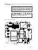
2.4 Stand-Alone Connection Diagram
The power supply range is 2.5 V to 5.5 V and isolated OUT+ and OUT– lines
for BTL operation are required.
Note that the source of any shutdown signal applied to the EVM SHUTDOWN
pin must be able to sink the current flowing through the pullup resistor on the
module (20 kΩ) when the pin is held low.
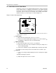
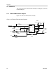
Figure 2–3 shows a TPA751 EVM connected for stereo BTL operation.
Figure 2–3. TPA751 EVMs Connected for Stereo BTL Output
Audio Input
(Left)
External Mute
Control
(active low)
5 VDC
Audio Input
(Right)
5 VDC GND
OUT+
IN–
IN+
VDD GND
U1
†
Shutdown
R5
OUT–
GND
C4
TEXAS
INSTRUMENTS
SLOP357
TPA751 MSOP EVM
C5
S1
R1
+
R2
C2
C1
R3
R4
C3
OUT+
IN–
IN+
VDD GND
U1
†
Shutdown
R5
OUT–
GND
C4
TEXAS
INSTRUMENTS
SLOP357
TPA751 MSOP EVM
C5
S1
R1
+
R2
C2
C1
R3
R4
C3
Right
Left
†
Due to the very small size of the MSOP IC package, the standard part number TPA751 is replaced with the code TIATC.