
User's Manual Stereo Amplifier TPA3008D2


Table Of Contents
- FEATURES
- DESCRIPTION
- APPLICATIONS
- ABSOLUTE MAXIMUM RATINGS
- DISSIPATION RATING TABLE
- RECOMMENDED OPERATING CONDITIONS
- AVAILABLE OPTIONS
- DC ELECTRICAL CHARACTERISTICS
- AC ELECTRICAL CHARACTERISTICS
- TYPICAL CHARACTERISTICS
- APPLICATION INFORMATION
- CLASS-D OPERATION
- Traditional Class-D Modulation Scheme
- TPA3008D2 Modulation Scheme
- Efficiency: LC Filter Required With the Traditional Class-D Modulation Scheme
- Effects of Applying a Square Wave Into a Speaker
- When to Use an Output Filter for EMI Suppression
- Gain setting via GAIN0 and GAIN1 inputs
- INPUT RESISTANCE
- INPUT CAPACITOR, CI
- SHUTDOWN OPERATION
- USING LOW-ESR CAPACITORS
- SHORT-CIRCUIT PROTECTION AND AUTOMATIC RECOVERY FEATURE
- THERMAL PROTECTION
- PRINTED-CIRCUIT BOARD (PCB) LAYOUT
- BASIC MEASUREMENT SYSTEM
- DIFFERENTIAL INPUT AND BTL OUTPUT
- CLASS-D RC LOW-PASS FILTER
www.ti.com
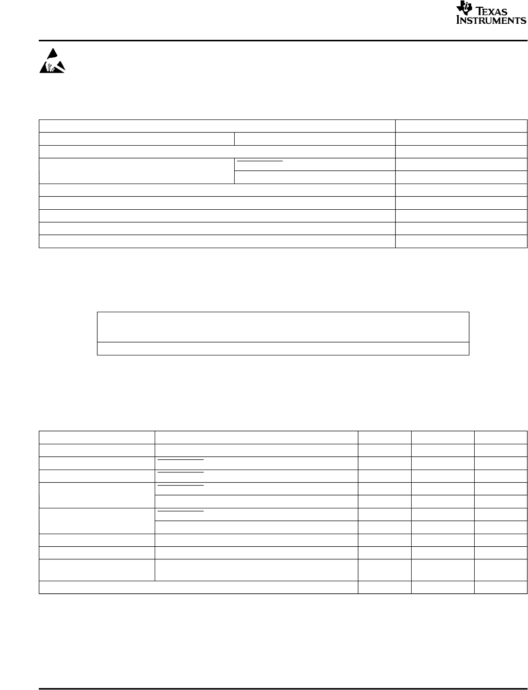
ABSOLUTE MAXIMUM RATINGS
DISSIPATION RATING TABLE
RECOMMENDED OPERATING CONDITIONS
TPA3008D2
SLOS435A – MAY 2004 – REVISED JULY 2004
These devices have limited built-in ESD protection. The leads should be shorted together or the device
placed in conductive foam during storage or handling to prevent electrostatic damage to the MOS gates.
over operating free-air temperature range (unless otherwise noted)
(1)
TPA3008D2
Supply voltage range AV
CC
, PV
CC
-0.3 V to 20 V
Load Impedance, R
L
≥ 6 Ω
SHUTDOWN -0.3 V to VCC + 0.3 V
Input voltage range, V
I
GAIN0, GAIN1, RINN, RINP, LINN, LINP -0.3 V to 6 V
Continuous total power dissipation See Dissipation Rating Table
Operating free–air temperature range, T
A
- 40°C to 85°C
Operating junction temperature range, T
J
- 40°C to 150°C
Storage temperature range, T
stg
- 65°C to 150°C
Lead temperature 1,6 mm (1/16 inch) from case for 10 seconds 260°C
(1) Stresses beyond those listed under “absolute maximum ratings” may cause permanent damage to the device. These are stress ratings
only, and functional operation of the device at these or any other conditions beyond those indicated under “recommended operating
conditions” is not implied. Exposure to absolute–maximum–rated conditions for extended periods may affect device reliability.
DERATING
PACKAGE T
A
≤ 25°C θ
JC
FACTOR T
A
= 70°C T
A
= 85°C
(1/θ
JA
)
PHP 4.3 W 1.14 °C/W
(1)
34.7 mW/°C
(1)
2.7 W 2.2 W
(1) Based on a JEDEC high-K PCB with the PowerPAD™ soldered to a thermal land on the
printed-circuit board. See the PowerPAD Thermally Enhanced Package application note (SLMA002).
The PowerPAD must be soldered to the PCB.
T
A
= 25°C (unless otherwise noted)
MIN MAX UNIT
Supply voltage, V
CC
PV
CC
, AV
CC
8.5 18 V
High-level input voltage, V
IH
SHUTDOWN, GAIN0, GAIN1 2 V
Low-level input voltage, V
IL
SHUTDOWN, GAIN0, GAIN1 0.8 V
SHUTDOWN, V
I
= V
CC
= 18 V 10 µA
High-level input current, I
IH
GAIN0, GAIN1, V
I
= 5.5 V, V
CC
= 18 V 1 µA
SHUTDOWN, V
I
= 0 V, V
CC
= 18 V 1 µA
Low-level input current, I
IL
GAIN0, GAIN1, V
I
= 5.5 V, V
CC
= 18 V 1 µA
High-level output voltage, V
OH
FAULT, I
OH
= 100 µA AV
DD
- 0.8 V V
Low-level output voltage, V
OL
FAULT, I
OL
= -100 µA AGND + 0.8 V V
Frequency is set by selection of ROSC and COSC
Oscillator frequency, f
OSC
200 300 kHz
(see the Application Information Section).
Operating free–air temperature, T
A
-40 85 °C
2