TPA0242 Audio Power Amplifier Evaluation Module User’s Guide March 2000 Mixed-Signal Products SLOU074
IMPORTANT NOTICE Texas Instruments and its subsidiaries (TI) reserve the right to make changes to their products or to discontinue any product or service without notice, and advise customers to obtain the latest version of relevant information to verify, before placing orders, that information being relied on is current and complete.
Preface Related Documentation From Texas Instruments J J TI Plug-N-Play Audio Amplifier Evaluation Platform (literature number SLOU011) provides detailed information on the evaluation platform and its use with TI audio evaluation modules. TPA0242 Stereo 2-W Audio Power Amplifier (literature number SLOS287) This is the data sheet for the TPA0242 audio amplifier integrated circuit. FCC Warning This equipment is intended for use in a laboratory test environment only.
iv
Running Title—Attribute Reference Contents 1 Introduction . . . . . . . . . . . . . . . . . . . . . . . . . . . . . . . . . . . . . . . . . . . . . . . . . . . . . . . . . . . . . . . . . . . . . 1.1 Feature Highlights . . . . . . . . . . . . . . . . . . . . . . . . . . . . . . . . . . . . . . . . . . . . . . . . . . . . . . . . . . 1.2 Description . . . . . . . . . . . . . . . . . . . . . . . . . . . . . . . . . . . . . . . . . . . . . . . . . . . . . . . . . . . . . . . . 1.
Running Title—Attribute Reference Figures 1–1 2–1 2–2 2–3 3–1 3–2 3–3 3–4 3–5 3–6 3–7 3–8 3–9 3–10 The TI TPA0242 Audio Amplifier Evaluation Module . . . . . . . . . . . . . . . . . . . . . . . . . . . . . . . 1-3 Quick Start Platform Map . . . . . . . . . . . . . . . . . . . . . . . . . . . . . . . . . . . . . . . . . . . . . . . . . . . . . . 2-2 Module Preparation . . . . . . . . . . . . . . . . . . . . . . . . . . . . . . . . . . . . . . . . . . . . . . . . . . . . . . . . . . .
Chapter 1 Introduction This chapter provides an overview of the Texas Instruments (TI) TPA0242 audio amplifier evaluation module (SLOP275). It includes a list of EVM features, a brief description of the module illustrated with a pictorial diagram, and a list of EVM specifications. Topic Page 1.1 Feature Highlights . . . . . . . . . . . . . . . . . . . . . . . . . . . . . . . . . . . . . . . . . . . . 1–2 1.2 Description . . . . . . . . . . . . . . . . . . . . . . . . . . . . . . . . . . . . . . . .
Feature Highlights 1.
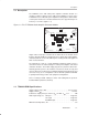
Description 1.2 Description The TPA0242 stereo 2-W audio power amplifier evaluation module is a complete, 2-watt per channel stereo audio power amplifier. It consists of the TI TPA0242 stereo 2-W audio power amplifier IC along with a small number of other parts mounted on a circuit board that measures approximately 2 1/4 inches by 1 1/2 inches (Figure 1–1). Figure 1–1.
1-4 Introduction
Chapter 2 Quick Start The steps in this chapter can be followed to quickly prepare the TPA0242 audio amplifier EVM for use. Using the TPA0242 with the TI plug-n-play audio amplifier evaluation platform is a quick and easy way to connect power, signal and control inputs, and signal outputs to the EVM using standard connectors.
Precautions 2.1 Precautions Power Supply Input Polarity and Maximum Voltage Always ensure that the polarity and voltage of the external power connected to VCC power input connector J1, J2, and/or VDD power input connector J6 are correct. Overvoltage or reverse-polarity power applied to these terminals can open onboard soldered-in fuses and cause other damage to the platform, installed evaluation modules, and/or the power source.
Quick Start List for Platform 2.2 Quick Start List for Platform Follow these steps when using the TPA0242 EVM with the TI plug-n-play audio amplifier evaluation platform (see the platform user’s guide, SLOU011, for additional details). Numbered callouts for selected steps are shown in Figure 2–1 and Figure 2–2, and details appear in Chapter 3. - Platform preparations 1) Ensure that all external power sources are set to OFF and that the platform power switch S1 is set to OFF.
Quick Start List for Platform - Evaluation module preparations Figure 2–2. Module Preparation VDD R HP GND + GND GND ROUT– S4 S3 S2 R4 R3 C6 C5 C4 C3 R LINE– SHUTDOWN R IN+ ROUT+ C10 HP/LINE SE/BTL S1 C11 R1 13 PCBEEP C1 C12 14 L IN+ 12 U1 C2 R2 TEXAS INSTRUMENTS 11 SHUTDOWN C9 C8 C7 L LINE– LOUT– GND + L HP VDD TPA00242 EVM Board GND C13 GND SLOP275 LOUT+ Table 2–4.
Quick Start List for Stand-Alone 2.3 Quick Start List for Stand-Alone Follow these steps to use the TPA0242 EVM stand-alone or when connecting it into existing circuits or equipment. Connections to the TPA0242 module header pins can be made via individual sockets, wire-wrapping, or soldering to the pins, either on the top or the bottom of the module circuit board. Numbered callouts for selected steps are shown in Figure 2–3 and details appear in Chapter 3. Figure 2–3.
Quick Start List for Stand-Alone - Evaluation module preparations 6) To allow the module SE/BTL control input to switch the amplifier IC between single ended (SE) and bridge-tied load (BTL) output modes, set output mode jumper S3 to OFF. To keep the module amplifier IC in the single-ended output mode regardless of the control input state, set jumper S3 to ON.
Chapter 3 Details This chapter provides details on the TPA0242 IC, the evaluation module, and the steps in the Quick-Start List, additional application information, and a parts list for the TPA0242 evaluation module. Topic Page 3.1 Precautions . . . . . . . . . . . . . . . . . . . . . . . . . . . . . . . . . . . . . . . . . . . . . . . . . . 3–2 3.2 The TPA0242 Audio Power Amplifier Evaluation Module . . . . . . . . . 3–3 3.3 Using the TPA0242 EVM With the Plug-N-Play Evaluation Platform . . . . .
Precautions 3.1 Precautions Power Supply Input Polarity and Maximum Voltage Always ensure that the polarity and voltage of the external power connected to VCC power input connector J1, J2, and/or VDD power input connector J6 are correct. Overvoltage or reverse-polarity power applied to these terminals can open onboard soldered-in fuses and cause other damage to the platform, installed evaluation modules, and/or the power source.
The TPA0242 Audio Power Amplifier Evaluation Module 3.2 The TPA0242 Audio Power Amplifier Evaluation Module The TPA0242 audio power amplifier evaluation module is powered by a TPA0242 stereo power amplifier capable of delivering greater than 2 W of continuous power per channel into 3-Ω loads. The amplifier IC can be operated in either the BTL or single-ended output mode.
The TPA0242 Audio Power Amplifier Evaluation Module Figure 3–3. TPA0242 EVM Schematic Diagram R2 50 kΩ 1 VDD CW 2 TP1 CCW 3 4 S4 L OUT + R1 100 kΩ PCB ENABLE RLINEIN VOLUME LOUT+ SHUTDOWN ROUT+ 5 C7 0.47 µF L HP 6 C8 0.47 µF VDD C12 10 µF 7 8 GND 9 C2 0.47 µF 10 R IN + 11 L OUT – C12 0.47 µF L IN + C9 0.47 µF 12 LLINEIN RHPIN LHPIN VDD PVDD PVDD RIN CLK LOUT– ROUT– LIN SE/BTL BYPASS GND PC–BEEP GND C1 0.47 µF R LINE – VDD 23 SHUTDOWN S1 22 SHUTDOWN 21 20 19 C4 0.
The TPA0242 Audio Power Amplifier Evaluation Module Figure 3–4. TPA0242 Amplifier IC L HP MUX L IN L LINE PC BEEP PC BEEP VOLUME CONTROL VOLUME R LINE R IN MUX R HP HP/LINE 3.2.2 SE/BTL Inputs and Gain Each channel has two separate signal inputs, line and headphone (HP ), that are automatically selected with the output mode (SE/BTL). An input multiplexor in the amplifier IC selects the HP inputs when the IC is in the SE output mode and the line inputs when in the BTL output mode.
The TPA0242 Audio Power Amplifier Evaluation Module Potentiometer R2 adjusts the gain of the internal preamp stage of the TPA0242 amplifier by adjusting the control voltage applied to the VOLUME terminal (pin 3) of the IC. Rotating the potentiometer slider clockwise decreases the applied control voltage, resulting in a higher volume. Table 3–1 shows the relationship between the control voltage applied to the VOLUME terminal and the effective amplifier gain. Headphone gain is reduced by 6 dB. Table 3–1.
The TPA0242 Audio Power Amplifier Evaluation Module 3.2.4 Depop Circuitry The TPA0242 amplifier IC contains internal circuitry to minimize the various transients that might appear at the output during the transition from power off or shutdown to normal operation, or when transitioning between the SE and BTL modes. 3.2.5 BTL Operation To operate in the bridge-tied load output mode, the module SE/BTL control input terminal must be held low.
Using The TPA0242 EVM With the Plug-N-Play Evaluation Platform 3.3 Using The TPA0242 EVM With the Plug-N-Play Evaluation Platform The TPA0242 audio amplifier evaluation module was designed to be used with the TI plug-n-play audio amplifier evaluation platform. It simply plugs into socket U2. The following paragraphs provide additional details for using the TPA0242 EVM with the platform. 3.3.
Using The TPA0242 EVM With the Plug-N-Play Evaluation Platform 3.3.2 TPA0242 Module Jumper Settings and Switches The TPA0242 EVM is equipped with a pushbutton SPST switch and a jumper that acts as an SPST switch to allow module operation to be modified to suit various requirements. In the following discussion, setting a jumper to ON means that a shunt is installed across the two pins of the jumper. Setting a jumper to OFF means that no shunt is installed on the jumper. See Figure 3.5.
Using The TPA0242 EVM With the Plug-N-Play Evaluation Platform 3.3.2.1 S1 — Shutdown Switch Pushbutton switch S1 on the EVM allows the manual shutdown of the TPA0242 amplifier IC. 3.3.2.2 S3 — Output Mode Jumper To keep the module amplifier IC in the single-ended output mode regardless of the module control input state, set jumper S3 to ON.
Using The TPA0242 EVM With the Plug-N-Play Evaluation Platform 3.3.3 Signal Routing Signal flow on the platform is controlled by two signal routing switches, as shown in Figure 3 – 6. Figure 3–6. Platform Signal Routing and Outputs Off + Audio Input R R R U1 Signal Conditioning S2 – U2 TPA0242 Amplifier EVM – L L L J7, J8, J9 Speaker Outputs + On U2 – U4 R U5 Stereo Headphone Amplifier R S3 + – J10 Headphone Output – GND L L + U5 3.3.3.
Using The TPA0242 EVM With the Plug-N-Play Evaluation Platform 3.3.4 Mute (Shutdown)/Mode The TPA0242 EVM is equipped with a shutdown control input pin. When this input is pulled to ground, the TPA0242 amplifier IC on the module enters the shutdown mode and dissipates very little power. While in the shutdown mode, the PC BEEP input is still active. When the EVM control input is tied to GND or allowed to float, normal amplifier operation resumes.
Using The TPA0242 EVM With the Plug-N-Play Evaluation Platform 3.3.4.2 Mute/Mode Select (JP6) A 3-pin jumper header (JP6) on the platform, functioning as an SPDT switch, routes the control signal from the headphone jack to either the shutdown control input pin or the mode control input pin of the evaluation module. J J 3.3.4.
Power Requirements 3.3.5 Power Requirements The TPA0242 audio power amplifier evaluation module can operate from any voltage between approximately 4.5 V and 5.5 V; however, the TPA0242 amplifier IC on the module is characterized for operation at 5 V. For best performance (highest output power with lowest distortion), the module should be operated at approximately 5 V unless there is a specific reason for operating it from a different voltage.
Inputs and Outputs 3.3.6 Inputs and Outputs The TI plug-n-play audio amplifier evaluation platform is equipped with several standard conectors for audio inputs and outputs. 3.3.6.1 Inputs In most cases, audio signals enter the platform through either a pair of RCA phono jacks (J3 and J5) or a miniature (1/8″) stereo phone jack (J4). Certain signal conditioning and amplifier EVMs, however, may have additional signal input connectors mounted on the module circuit board.
Using The TPA0242 EVM Stand-Alone 3.4 Using The TPA0242 EVM Stand-Alone Using the TPA0242 audio power amplifier evaluation module stand-alone is much the same as using it with the platform. The same 4.5-V to 5.5-V power supply range and the isolated OUT+ and OUT– lines for BTL operation requirement exists. Note that the shutdown signal applied to the EVM SHUTDOWN pin must be able to supply enough current to overcome the pullup resistor on the module (100 kΩ). 3.4.
Using The TPA0242 EVM Stand-Alone 3.4.2 TPA0242 EVM Connected for Single-Ended Output Figure 3–10.
TPA0242 Audio Power Amplifier Evaluation Module Parts List 3.5 TPA0242 Audio Power Amplifier Evaluation Module Parts List Table 3–4. TPA0242 EVM Parts List Reference Description Size EVM Qty. Manufacturer/ Part Number Digi-Key Number C5 Capacitor, 0.1 µF, 10%, nonpolarized 0805 1 Murata GRM40-X7R104K25 C1, C2, C3, C4, C7, C8, C9, C11, C12 Capacitor, 0.47 µF, 80%/–20%, nonpolarized 0805 9 Murata GRM40-Y5V474Z16 C6 Capacitor, 0.