
Datasheet


SLOS278D − JANUARY 2000 − REVISED NOVEMBER 2002
3
POST OFFICE BOX 655303 • DALLAS, TEXAS 75265
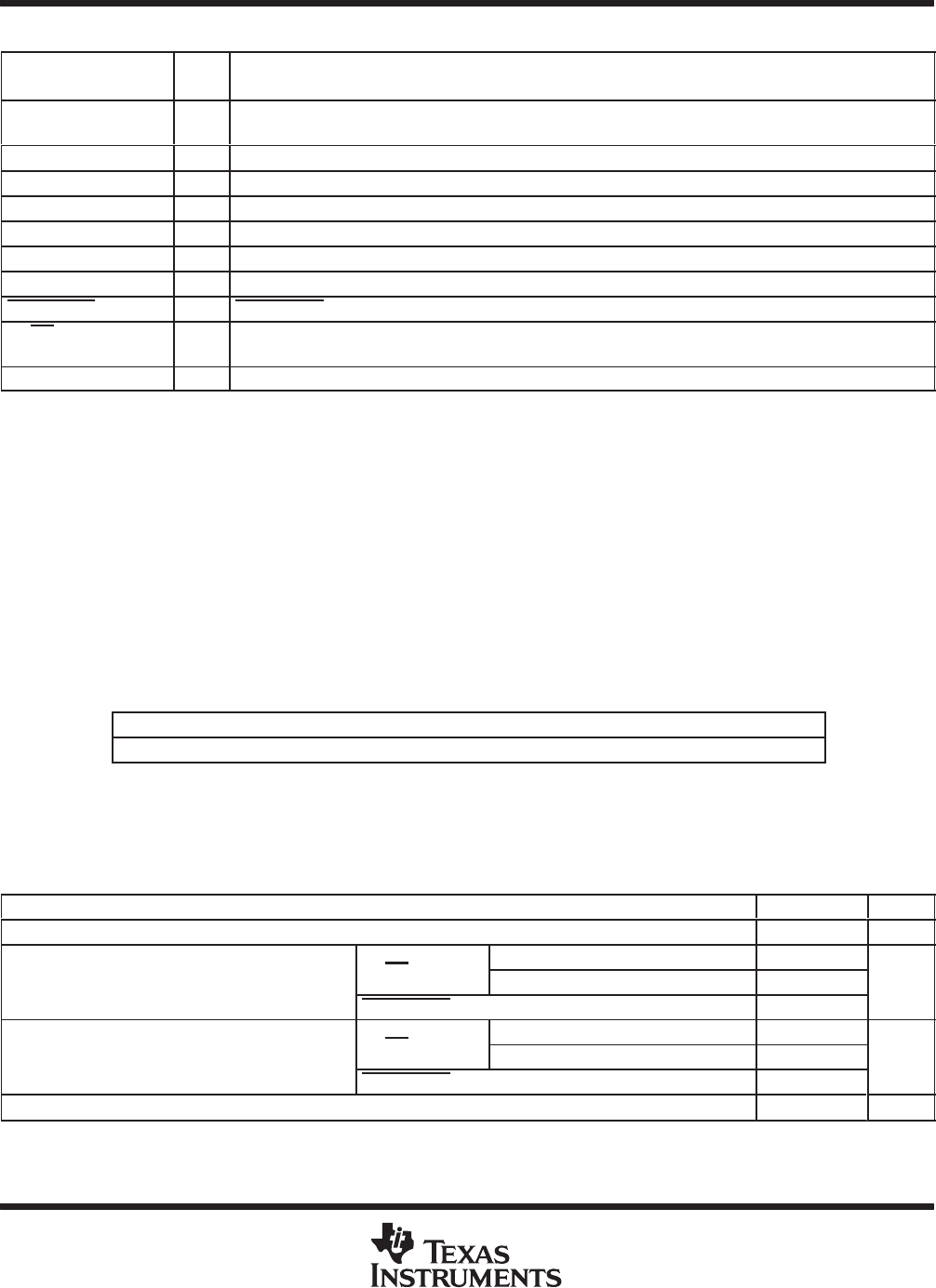
Terminal Functions
TERMINAL
I/O
DESCRIPTION
NAME NO.
I/O
DESCRIPTION
BYPASS 4 I BYPASS is the tap to the voltage divider for internal mid-supply bias. This terminal should be connected
to a 0.1-µF to 1-µF capacitor.
FILT_CAP 1 I Terminal is used to filter supply.
GND 8 Ground terminal
LIN 9 I Left-channel input terminal
LO/MO− 10 O Left-output in SE mode and mono negative output in BTL mode.
RIN 5 I Right-channel input terminal
RO/MO+ 6 O Right-output in SE mode and mono positive output in BTL mode
SHUTDOWN 2 I SHUTDOWN places the entire device in shutdown mode when held low. TTL compatible input.
ST/MN 7 I Selects between stereo and mono mode. When held high, the amplifier is in SE stereo mode, while held
low, the amplifier is in BTL mono mode.
V
DD
3 I V
DD
is the supply voltage terminal.
absolute maximum ratings over operating free-air temperature range (unless otherwise noted)
†
Supply voltage, V
DD
6 V. . . . . . . . . . . . . . . . . . . . . . . . . . . . . . . . . . . . . . . . . . . . . . . . . . . . . . . . . . . . . . . . . . . . . . . .
Input voltage range, V
I
−0.3 V to V
DD
+0.3 V. . . . . . . . . . . . . . . . . . . . . . . . . . . . . . . . . . . . . . . . . . . . . . . . . . . . . . .
Continuous total power dissipation internally limited (see Dissipation Rating Table). . . . . . . . . . . . . . . . . . . . .
Operating free-air temperature range, T
A
(see Table 3) −40°C to 85°C. . . . . . . . . . . . . . . . . . . . . . . . . . . . . . . .
Operating junction temperature range, T
J
−40°C to 150°C. . . . . . . . . . . . . . . . . . . . . . . . . . . . . . . . . . . . . . . . . . .
Storage temperature range, T
stg
−65°C to 150°C. . . . . . . . . . . . . . . . . . . . . . . . . . . . . . . . . . . . . . . . . . . . . . . . . . .
Lead temperature 1,6 mm (1/16 inch) from case for 10 seconds 260°C. . . . . . . . . . . . . . . . . . . . . . . . . . . . . . .
†
Stresses beyond those listed under “absolute maximum ratings” may cause permanent damage to the device. These are stress ratings only, and
functional operation of the device at these or any other conditions beyond those indicated under “recommended operating conditions” is not
implied. Exposure to absolute-maximum-rated conditions for extended periods may affect device reliability.
DISSIPATION RATING TABLE
PACKAGE
T
A
≤ 25°C DERATING FACTOR T
A
= 70°C T
A
= 85°C
DGQ 2.14 W
‡
17.1 mW/°C 1.37 W 1.11 W
‡
See the Texas Instruments document, PowerPAD Thermally Enhanced Package Application Report
(SLMA002), for more information on the PowerPAD package. The thermal data was measured on a PCB
layout based on the information in the section entitled Texas Instruments Recommended Board for PowerPAD
on page 33 of that document.
recommended operating conditions
MIN MAX UNIT
Supply voltage, V
DD
2.5 5.5 V
ST/MN
V
DD
= 3 V 2.7
High-level input voltage, V
IH
ST/MN
V
DD
= 5 V 4.5
V
High-level input voltage, V
IH
SHUTDOWN 2
V
ST/MN
V
DD
= 3 V 1.65
Low-level input voltage, V
IL
ST/MN
V
DD
= 5 V 2.75
V
Low-level input voltage, V
IL
SHUTDOWN 0.8
V
Operating free-air temperature, T
A
−40 85 °C
PowerPAD is a trademark of Texas Instruments.