
Datasheet


SLOS278D − JANUARY 2000 − REVISED NOVEMBER 2002
15
POST OFFICE BOX 655303 • DALLAS, TEXAS 75265
APPLICATION INFORMATION
bridged-tied load versus single-ended mode (continued)
In a typical computer sound channel operating at 5 V, bridging raises the power into an 8-Ω speaker from a
singled-ended (SE, ground reference) limit of 250 mW to 1 W. In sound power, that is a 6-dB improvement—
which is loudness that can be heard. In addition to increased power, there are frequency response concerns.
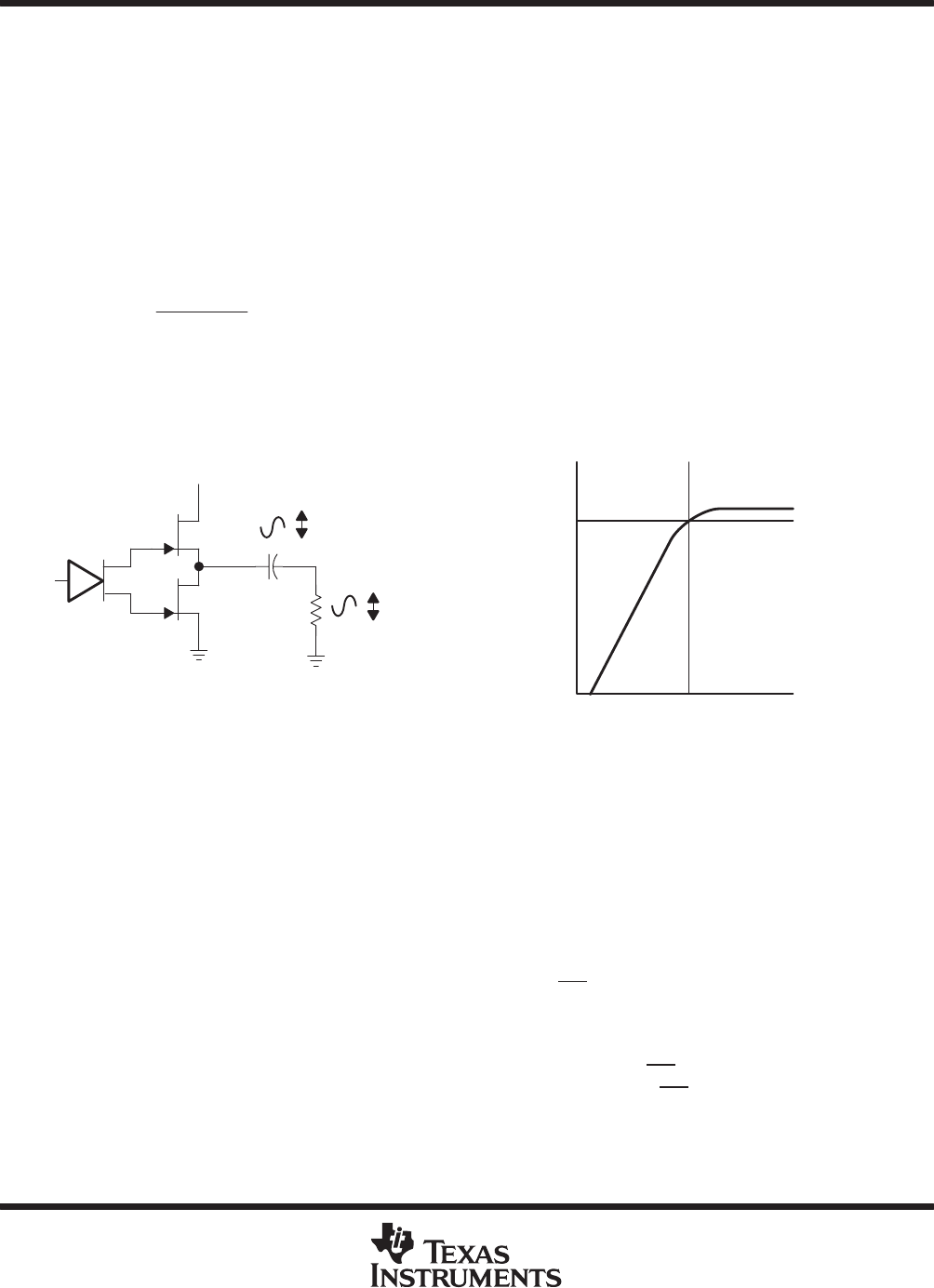
Consider the single-supply SE configuration shown in Figure 25. A coupling capacitor is required to block the
dc offset voltage from reaching the load. These capacitors can be quite large (approximately 33 µF to 1000 µF)
so they tend to be expensive, heavy, occupy valuable PCB area, and have the additional drawback of limiting
low-frequency performance of the system. This frequency limiting effect is due to the high-pass filter network
created with the speaker impedance and the coupling capacitance and is calculated with equation 8.
f
c
+
1
2p R
L
C
(C)
(8)
For example, a 68-µF capacitor with an 8-Ω speaker would attenuate low frequencies below 293 Hz. The BTL
configuration cancels the dc offsets, which eliminates the need for the blocking capacitors. Low-frequency
performance is then limited only by the input network and speaker response. Cost and PCB space are also
minimized by eliminating the bulky coupling capacitor.
R
L
C
(C)
V
O(PP)
V
O(PP)
V
DD
−3 dB
f
c
Figure 25. Single-Ended Configuration and Frequency Response
Increasing power to the load does carry a penalty of increased internal power dissipation. The increased
dissipation is understandable considering that the BTL configuration produces 4× the output power of the SE
configuration. Internal dissipation versus output power is discussed further in the crest factor and thermal
considerations section.
single-ended (stereo) operation
In SE (stereo) mode (see Figure 24 and Figure 25), the load is driven from the primary amplifier output for each
channel (LO and RO, terminals 6 and 10).
The amplifier switches to single-ended operation when the ST/MN terminal is held high.
input operation
The input allows stereo inputs to be applied to the amplifier. When the ST/MN terminal is held high, the inputs
(LIN and RIN) drive the outputs as LO and RO in stereo mode. When the ST/MN
terminal is held low, the inputs
are surrounded internally to create the mono BTL signal, driving the outputs as MO+ and MO−.