
Serial RapidIO (SRIO) User's Guide

www.ti.com
2.3.10.1 Reset and Power Down Summary
2.3.10.2 Enable and Enable Status Registers
SRIO Functional Description
After reset, the state of the peripheral depends on the default register values.
Software can also perform a hard reset of each logical block within the peripheral via the GBL_EN and
BLK n_EN bits. The GBL_EN bit resets the peripheral, while the rest of the device is not reset. The
BLK n_EN bits shut down unused portions of the peripheral, which minimizes power by resetting the
appropriate logical block(s) and gating off the clock to the appropriate logical block(s). This should be
considered an abrupt reset that is independent of the state of the peripheral and that resets the peripheral
to its original state.
Upon reset of the peripheral, the device must reestablish communication with its link partner. Depending
on the system, this may include a discovery phase in which a host processor reads the peripheral’s
CAR/CSR registers to determine its capabilities. In its simplest form, it involves retraining the SERDES
and going through the initialization phase to synchronize on bit and word boundaries by using idle and
control symbols, as described in Section 5.5.2 of the Part VI of the RapidIO Interconnect Specification.
Until the peripheral and its partner are fully initialized and ready for normal operation, the peripheral will
not send any data packets or non-status control symbols.
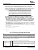
• GBL_EN: Resets all MMRs, excluding Reset Ctl Values (0000h–01FCh). Resets all logical blocks
except MMR configuration bus i/f. While asserted, the slave configuration bus is operational.
• BLK_EN0: Resets all MMRs, excluding Reset Ctl Values (0000h–01FCh). Other logical blocks are
unaffected, including MMR configuration bus i/f.
• BLK_EN[n:1]: Single enable/reset per logical block. See Table 26 .
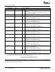
The enable and enable status registers are comprised of two global registers and nine pairs of
block-specific registers. The global registers are summarized by Figure 32 , Figure 33 , Table 26 , and
Table 27 . The GBL_EN register is implemented with a single enable bit. This bit is logically ORed with the
reset input to the module and is fanned out to all logical blocks within the peripheral.
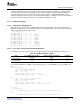
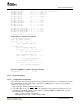
Figure 32. GBL_EN (Address 0030h)
31 1 0
Reserved EN
R-0 R/W-1
LEGEND: R/W = Read/Write; R = Read only; - n = Value after reset
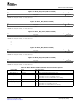
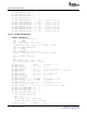
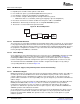
Figure 33. GBL_EN_STAT (Address 0034h)
31 24
Reserved
R-0
23 16
Reserved
R-0
15 10 9 8
Reserved BLK8_EN_ BLK7_EN_
STAT STAT
R-0 R-1 R-1
7 6 5 4 3 2 1 0
BLK6_EN_ BLK5_EN_ BLK4_EN_ BLK3_EN_ BLK2_EN_ BLK1_EN_ BLK0_EN_ GBL_EN_
STAT STAT STAT STAT STAT STAT STAT STAT
R-1 R-1 R-1 R-1 R-1 R-1 R-1 R-1
LEGEND: R = Read only; - n = Value after reset
SPRUE13A – September 2006 Serial RapidIO (SRIO) 71
Submit Documentation Feedback