
Serial RapidIO (SRIO) User's Guide

www.ti.com
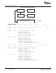
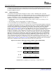
acklD rsv prio tt 1010 destID sourcelD Reserved srcTID
Reserved DoorbellReg# rsv
Doorbellbit
CRC
PHYLOGTRALOGTRAPHY
5 3 2 2 4 8 8 8 8
9 2
1
4
16
1632
16
4
2
10
info(msb)
8
info(lsb)
8
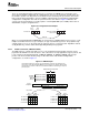
SRIO Functional Description
for any desired purpose; see the RapidIO Interconnect Specification, Section 3.1.4, Type 10 Packet
Formats (Doorbell Class), for information about the info field. A processing element that receives a
doorbell transaction takes the packet and puts it in a doorbell message queue within the processing
element. This queue may be implemented in hardware or in local memory. This behavior is similar to that
of typical message passing mailbox hardware. The local processor is expected to read the queue to
determine the sending processing element and the info field, and determine what action to take.
The DOORBELL functionality is user-defined, but this packet type is commonly used to initiate DSP core
(CPU) interrupts. A DOORBELL packet is not associated with a particular data packet that was previously
transferred, so the info field of the packet must be configured to reflect the DOORBELL bit to be serviced
for the correct TID (Transfer Information Descriptor) information to be processed.
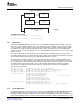
Figure 26. Doorbell Operation
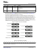
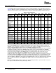
The DOORBELL packet’s 16-bit INFO field indicates which DOORBELL register interrupt bit to set. There
are four DOORBELL registers, each currently with 16 bits, allowing 64 interrupt sources or circular buffers
(see Table 23 ). Each bit can be assigned to any core as described below by the Interrupt Condition
Routing Registers. Additionally, each status bit is user-defined for the application. For instance, it may be
desirable to support multiple priorities with multiple TID circular buffers per core if control data uses a high
priority (for example, priority = 2), while data packets are sent on priority 0 or 1. This allows the control
packets to have preference in the switch fabric and arrive as quickly as possible. Since it may be required
to interrupt the CPU for both data and control packet processing separately, separate circular buffers are
used, and DOORBELL packets need to distinguish between them for interrupt servicing. If any reserved
bit in the DOORBELL info field is set, an error response is sent.
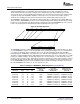
Table 23. Examples of DOORBELL_INFO Designations (See Figure 26 )
info Field Segments Value Written To
DOORBELL_INFO Associated Mapped To This
Doorbell Doorbell Field Of Doorbell Interrupt Doorbell Interrupt
Reserved Reg # rsv Bit LSUn_REG5 Routing Bits Status Bit
000000000b 00b 0b 0000b 0000h DOORBELL0_ICRR[3:0] DOORBELL0_ICSR[0]
000000000b 00b 0b 1001b 0009h DOORBELL0_ICRR2[7:4] DOORBELL0_ICSR[9]
000000000b 01b 0b 0111b 0027h DOORBELL1_ICRR[31:28] DOORBELL1_ICSR[7]
000000000b 01b 0b 1100b 002Ch DOORBELL1_ICRR2[19:16] DOORBELL1_ICSR[12]
000000000b 10b 0b 0101b 0045h DOORBELL2_ICRR[23:20] DOORBELL2_ICSR[5]
000000000b 10b 0b 1111b 004Fh DOORBELL2_ICRR2[31:28] DOORBELL2_ICSR[15]
000000000b 11b 0b 0110b 0066h DOORBELL3_ICRR[27:24] DOORBELL3_ICSR[6]
000000000b 11b 0b 1011b 006Bh DOORBELL3_ICRR2[15:12] DOORBELL3_ICSR[11]
Serial RapidIO (SRIO)64 SPRUE13A – September 2006
Submit Documentation Feedback