
Serial RapidIO (SRIO) User's Guide

www.ti.com
2.3.2.2 Enabling the Receiver
SRIO Functional Description
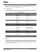
Table 6. Line Rate versus PLL Output Clock Frequency
Rate Line Rate PLL Output Frequency RATESCALE
Full x Gbps 0.5x GHz 0.5
Half x Gbps x GHz 1
Quarter x Gbps 2x GHz 2
RIOCLK and RIOCLK
FREQ
= LINERATE × RATESCALE
MPY
The rate is defined by the RATE bits of the SERDES_CFGRX n_CNTL register and the
SERDES_CFGTX n_CNTL register, respectively.
The primary operating frequency of the SERDES macro is determined by the reference clock frequency
and PLL multiplication factor. However, to support lower frequency applications, each receiver and
transmitter can also be configured to operate at a half or quarter of this rate via the RATE bits of the
SERDES_CFGRX n_CNTL and SERDES_CFGTX n_CNTL registers as described in Table 7 .
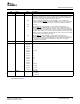
Table 7. Effect of the RATE Bits
RATE Description
00b Full rate. Two data samples taken per PLL output clock cycle.
01b Half rate. One data sample taken per PLL output clock cycle.
10b Quarter rate. One data sample taken every two PLL output clock cycles.
11b Reserved.
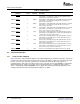
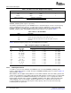
Table 8 shows the frequency range versus the multiplication factor (MPY).
Table 8. Frequency Range versus MPY Value
RIOCLK and RIOCLK Line Rate Range (Gbps)
MPY Range (MHz) Full Half Quarter
4x 250 - 425 2 - 3.4 1 - 1.7 0.5 - 0.85
5x 200 - 425 2 - 4.25 1 - 2.125 0.5 - 1.0625
6x 167 - 354.167 2 - 4.25 1 - 2.125 0.5 - 1.0625
8x 125 - 265.625 2 - 4.25 1 - 2.125 0.5 - 1.0625
10x 100 - 212.5 2 - 4.25 1 - 2.125 0.5 - 1.0625
12x 83.33 - 177.08 2 - 4.25 1 - 2.125 0.5 - 1.0625
12.5x 80 - 170 2 - 4.25 1 - 2.125 0.5 - 1.0625
15x 66.67 - 141.67 2 - 4.25 1 - 2.125 0.5 - 1.0625
20x 50 - 106.25 2 - 4.25 1 - 2.125 0.5 - 1.0625
25x 40 - 85 2 - 4.25 1 - 2.125 0.5 - 1.0625
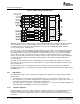
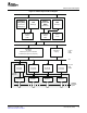
To enable a receiver for deserialization, the ENRX bit of the associated SERDES_CFGRX n_CNTL
registers (100h–10Ch) must be set high. The fields of SERDES_CFGRX n_CNTL are shown in Figure 10
and described in Table 9 .
When ENRX is low, all digital circuitry within the receiver will be disabled, and clocks will be gated off. All
current sources within the receiver will be fully powered down, with the exception of those associated with
the loss of signal detector and IEEE1149.6 boundary scan comparators. Loss of signal power down is
independently controlled via the LOS bits of SERDES_CFGRX n_CNTL. When enabled, the differential
signal amplitude of the received signal is monitored. Whenever loss of signal is detected, the clock
recovery algorithm is frozen to prevent the phase and frequency of the recovered clock from being
modified by low level signal noise.
30 Serial RapidIO (SRIO) SPRUE13A – September 2006
Submit Documentation Feedback