
Serial RapidIO (SRIO) User's Guide

www.ti.com
5.34 LSU n Control Register 1 (LSU n_REG1)
SRIO Registers
There are four of these registers, one for each LSU (see ). This register's content is shown in Figure 95
and described in Table 90 . For additional programming see Section 2.3.3 .
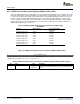
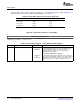
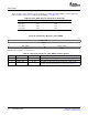
Table 89. LSU n_REG1 Registers and the Associated LSUs
Register Address Offset Associated LSU
LSU1_REG1 0404h LSU1
LSU2_REG1 0424h LSU2
LSU3_REG1 0444h LSU3
LSU4_REG1 0464h LSU4
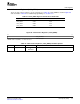
Figure 95. LSU n Control Register 1 (LSU n_REG1)
31 0
ADDRESS_LSB/CONFIG_OFFSET
R/W-00000000h
LEGEND: R/W = Read/Write; - n = Value after reset
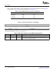
Table 90. LSU n Control Register 1 (LSU n_REG1) Field Descriptions
Bit Field Value Description
31–0 ADDRESS_LSB/CONFIG_OFFSET 00000000h For packet types 2, 5, and 6:
to The 32-bit destination address or the 32 least significant bits of
FFFFFFFFh an extended destination address. This value is used in
conjunction with BYTE_COUNT to create a 64-bit aligned
RapidIO packet header address.
For packet type 8 (maintenance packet):
00000000h The right-aligned 24-bit register configuration offset. This value is
to used in conjunction with BYTE_COUNT to create a 64-bit aligned
00FFFFFFh RapidIO packet header Config_offset value. The 2 LSBs of this
field must be 0s because the smallest configuration access is 4
bytes.
Serial RapidIO (SRIO)156 SPRUE13A – September 2006
Submit Documentation Feedback