
Serial RapidIO (SRIO) User's Guide

www.ti.com
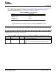
5.16 DOORBELL n Interrupt Condition Status Register (DOORBELL n_ICSR)
SRIO Registers
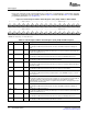
The four doorbell interrupts are mapped to these registers (see Table 65 ). The general form of a doorbell
interrupt condition status register is shown in Figure 77 and described in Table 66 . For additional
programming information, see Section 4.3.1 and Section 2.3.6 .
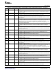
Table 65. DOORBELL n_ICSR Registers
Register Address Offset
DOORBELL0_ICSR 0200h
DOORBELL1_ICSR 0210h
DOORBELL2_ICSR 0220h
DOORBELL3_ICSR 0230h
Figure 77. Doorbell n Interrupt Condition Status Register (DOORBELL n_ICSR)
31 16
Reserved
R-0
15 14 13 12 11 10 9 8 7 6 5 4 3 2 1 0
ICS15 ICS14 ICS13 ICS12 ICS11 ICS10 ICS9 ICS8 ICS7 ICS6 ICS5 ICS4 ICS3 ICS2 ICS1 ICS0
R/W-0 R/W-0 R/W-0 R/W-0 R/W-0 R/W-0 R/W-0 R/W-0 R/W-0 R/W-0 R/W-0 R/W-0 R/W-0 R/W-0 R/W-0 R/W-0
LEGEND: R/W = Read/Write; R = Read only; - n = Value after reset
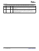
Table 66. DOORBELL n Interrupt Condition Status Register (DOORBELL n_ICSR) Field Descriptions
Bit Field Value Description
31–16 Reserved 0 These read-only bits return 0s when read.
15–0 ICS x Doorbell n interrupt condition status bit
(x = 15 to 0)
0 Bit x of the doorbell information value is 0.
1 Bit x of the doorbell information value is 1, generating an interrupt request.
Serial RapidIO (SRIO)132 SPRUE13A – September 2006
Submit Documentation Feedback