
Network Card User Manual


MTCLK
MTXD[3−0]
MTXEN
MCOL
MCRS
MRCLK
MRXD[3−0]
MRXDV
MRXER
MDCLK
MDIO
2.5 MHZ
or
25 MHz
Physical
layer
device
(PHY)
System
core
EMAC
MDIO
Transformer
RJ-45
EMAC Functional Architecture
www.ti.com
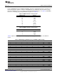
Table 6. MACSEL0[2:0], MACSEL1[1:0], and EMAC1_EN Decoding (continued)
MACSEL02 MACSEL01 MACSEL00 MACSEL11 MACSEL10 EMAC_EN EMAC0 EMAC1
1 0 0 1 1 1 None RMII
1 0 1 0 0 1 S3MII None
1 0 1 0 1 1 S3MII S3MII
1 0 1 1 0 1 S3MII RGMII
1 0 1 1 1 1 S3MII RMII
1 1 1 X X 0 None None
1 1 1 0 0 1 None None
1 1 1 0 1 1 None S3MII
1 1 1 1 0 1 None RGMII
1 1 1 1 1 1 None RMII
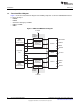
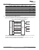
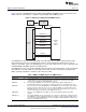
2.3.1 Media Independent Interface (MII) Connections
Figure 2 shows a TCI6486/C6472 device with integrated EMAC and MDIO interfaced to the PHY via an
MII connection. This interface is only available in 10 Mbps and 100 Mbps modes.
Figure 2. Ethernet Configuration with MII Interface
Table 7 summarizes the individual EMAC and MDIO signals for the MII interface. For more information,
refer to either the IEEE 802.3 standard or ISO/IEC 8802-3:2000(E).
The EMAC module does not include a transmit error (MTXER) pin. If a transmit error occurs, CRC
inversion is used to negate the validity of the transmitted frame.
18
C6472/TCI6486 EMAC/MDIO SPRUEF8F–March 2006–Revised November 2010
Submit Documentation Feedback
Copyright © 2006–2010, Texas Instruments Incorporated