
Video Port/VCXO Interpolated Control (VIC) Port User's Guide

www.ti.com
3.13.20 TCI System Time Clock Ticks Interrupt Register (TCITICKS)
Video Capture Registers
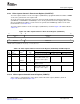
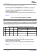
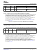
Figure 3-39. TCI System Time Clock Compare Mask MSB Register (TCISTMSKM)
31 16
Reserved
R-0
15 1 0
Reserved ATCM
R-0 R/W-0
LEGEND: R/W = Read/Write; R = Read only; - n = value after reset
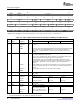
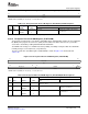
Table 3-32. TCI System Time Clock Compare Mask MSB Register (TCISTMSKM) Field Descriptions
Description
Bit field symval
(1)
Value BT.656, Y/C Mode, or Raw Data Mode TCI M ode
31-1 Reserved - 0 Reserved. The reserved bit location is always read as 0. A value written to this field
has no effect.
0 ATCM OF( value) 0-1 Not used. Contains the MSB of the absolute time
compare mask.
DEFAULT 0
(1)
For CSL implementation, use the notation VP_TCISTMSKM_ATCM_ symval
The transport stream interface system time clock ticks interrupt register (TCITICKS) is used to generate
an interrupt after a certain number of ticks of the 27-MHz system time clock. When the TICKCT value is
set to X and the TCKEN bit in TCICTL is set, the TICK bit in VPIS is set every X + 1 STCLK cycles. Note
that the tick interrupt counter and comparison logic function are separate from the PCR logic and always
count STCLK cycles regardless of the value of the CTMODE bit in TCICTL.
A write to TCITICKS resets the tick counter 0. Whenever the tick counter reaches the TICKCT value, the
TICK bit in VPIS is set and the counter resets to 0.
To prevent inaccurate comparisons caused by changing register bits, the software should disable the tick
count interrupt (clear the TCKEN bit in TCICTL) prior to writing to TCITICKS.
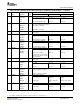
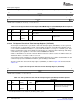
The TCI system time clock ticks interrupt register (TCITICKS) is shown in Figure 3-40 and described in
Table 3-33 .
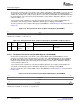
Figure 3-40. TCI System Time Clock Ticks Interrupt Register (TCITICKS)
31 0
TICKCT
R/W-0
LEGEND: R/W = Read/Write; - n = value after reset
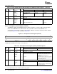
Table 3-33. TCI System Time Clock Ticks Interrupt Register (TCITICKS) Field Descriptions
Description
BT.656, Y/C Mode, or Raw Data TCI Mode
Bit field symval
(1)
Value Mode
31-0 TICKCT OF( value) 0-FFFF FFFFh Not used. Contains the number of ticks of the
27-MHz system time clock required to
generate a tick count interrupt.
DEFAULT 0
(1)
For CSL implementation, use the notation VP_TCITICKS_TICKCT_ symval
Video Capture Port90 SPRUEM1 – May 2007
Submit Documentation Feedback