
Video Port/VCXO Interpolated Control (VIC) Port User's Guide

www.ti.com
3.13.12 TCI Clock Initialization LSB Register (TCICLKINITL)
Video Capture Registers
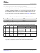
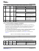
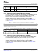
Table 3-24. TCI Capture Control Register (TCICTL) Field Descriptions (continued)
Description
Bit field
(1)
symval
(1)
Value BT.656, Y/C Mode, or Raw Data Mode TCI Mode
3 STEN OF( value) System time clock interrupt enable bit.
DEFAULT 0 Not used. Setting of the STC bit is disabled.
DISABLE
SET Not used. A valid STC compare sets the STC bit in
VPIS.
2 CTMODE OF( value) Counter mode select bit.
DEFAULT 0 Not used. The 33-bit PCR portion of the system time
counter increments at 90 kHz (when
90KHZ
PCRE rolls over from 299 to 0).
STCLK Not used. The 33-bit PCR portion of the system time
counter increments by the STCLK input.
1 ERRFILT OF( value) Error filtering enable bit.
DEFAULT 0 Not used. Packets with errors are received and the
PERR bit is set in the timestamp inserted
ACCEPT
at the end of the packet.
REJECT Not used. Packets with errors are filtered out (not
received in the FIFO).
0 Reserved - 0 Reserved. The reserved bit location is always read as 0. A value written to this field
has no effect.
The transport stream interface clock initialization LSB register (TCICLKINITL) is used to initialize the
hardware counter to synchronize with the system time clock. .
On receiving the first packet containing a program clock reference (PCR) and the PCR extension value,
the DSP writes the 32 least-significant bits (LSBs) of the PCR into TCICLKINITL. This initializes the
counter to the system time clock. TCICLKINITL should also be updated by the DSP whenever a
discontinuity in the PCR field is detected.
To ensure synchronization and prevent false compare detection, the software should disable the system
time clock interrupt (clear the STEN bit in TCICTL) prior to writing to TCICLKINITL. All bits of the system
time counter are initialized whenever either TCICLKINITL or TCICLKINITM are written.
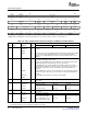
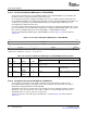
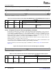
The TCI clock initialization LSB register (TCICLKINITL) is shown in Figure 3-32 and described in
Table 3-25
Figure 3-32. TCI Clock Initialization LSB Register (TCICLKINITL)
31 0
INPCR
R/W-0
LEGEND: R/W = Read/Write; - n = value after reset
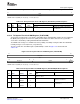
Table 3-25. TCI Clock Initialization LSB Register (TCICLKINITL) Field Descriptions
Description
Bit field symval
(1)
Value BT.656, Y/C Mode, or Raw Data Mode TCI Mode
31-0 INPCR OF( value) 0-FFFF FFFFh Not used. Initializes the 32 LSBs of the system
time clock.
DEFAULT 0
(1)
For CSL implementation, use the notation VP_TCICLKINITL_INPCR_ symval
SPRUEM1 – May 2007 Video Capture Port 85
Submit Documentation Feedback