
Video Port/VCXO Interpolated Control (VIC) Port User's Guide

www.ti.com
3.13.9 Video Capture Channel x Event Count Register (VCxEVTCT)
3.13.10 Video Capture Channel B Control Register (VCBCTL)
Video Capture Registers
The video capture channel x event count register (VCxEVTCT) is programmed with the number of EDMA
events to be generated for each capture field.
An event counter tracks how many events have been generated and indicates which threshold value
(VCTHRLD1 or VCTHRLD2 in VC xTHRLD) to use in event generation and in the outgoing data counter.
Once the CAPEVTCT n number of events have been generated, the EDMA logic switches to the other
threshold value. See Section 2.3.1 .
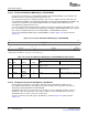
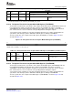
The video capture channel x event count register (VC xEVTCT) is shown in Figure 3-29 and described in
Table 3-22 .
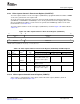
Figure 3-29. Video Capture Channel x Event Count Register (VCxEVTCT)
31 28 27 16
Reserved CAPEVTCT2
R-0 R/W-0
15 12 11 0
Reserved CAPEVTCT1
R-0 R/W-0
LEGEND: R/W = Read/Write; R = Read only; - n = value after reset
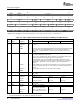
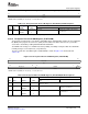
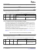
Table 3-22. Video Capture Channel x Event Count Register (VCxEVTCT) Field Descriptions
Description
Bit field
(1)
symval
(1)
Value BT.656 or Y/C Mode Raw Data Mode TCI Mode
31-28 Reserved - 0 Reserved. The reserved bit location is always read as 0. A value written to this
field has no effect.
27-16 CAPEVTCT2 OF( value) 0-FFFh Number of EDMA event sets Not used. Not used.
(YEVT, CbEVT, CrEVT) to be
generated for field 2 capture.
DEFAULT 0
15-12 Reserved - 0 Reserved. The reserved bit location is always read as 0. A value written to this
field has no effect.
11-0 CAPEVTCT1 OF( value) 0-FFFh Number of EDMA event sets Not used. Not used.
(YEVT, CbEVT, CrEVT) to be
generated for field 1 capture.
DEFAULT 0
(1)
For CSL implementation, use the notation VP_VC xEVTCT_CAPEVTCT n_ symval
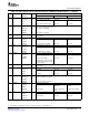
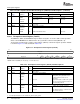
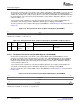
Video capture is controlled by the video capture channel B control register (VCBCTL) shown in
Figure 3-30 and described in Table 3-23 .
SPRUEM1 – May 2007 Video Capture Port 81
Submit Documentation Feedback