
Video Port/VCXO Interpolated Control (VIC) Port User's Guide


www.ti.com
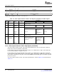
3.13.3 Video Capture Channel x Field 1 Start Register (VCxSTRT1)
Video Capture Registers
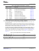
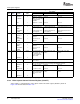
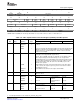
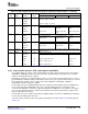
Table 3-15. Video Capture Channel A Control Register (VCACTL) Field Descriptions (continued)
Description
Bit field
(1)
symval
(1)
Value BT.656 or Y/C Mode Raw Data Mode TCI Mode
7 CON
(2)
OF( value) Continuous capture enable bit.
DEFAULT 0 Continuous capture is disabled.
DISABLE
ENABLE 1 Continuous capture is enabled.
6 FRAME
(2)
OF( value) Capture frame (data) bit.
DEFAULT 0 Do not capture frame. Do not capture single Do not capture single
data block. packet.
NONE
FRMCAP 1 Capture frame. Capture single data Capture single packet.
block.
5 CF2
(2)
OF( value) Capture field 2 bit.
NONE 0 Do not capture field 2. Do not capture field 2. Not used.
DEFAULT 1 Capture field 2. Capture field 2. Not used.
FLDCAP
4 CF1
(2)
OF( value) Capture field 1 bit.
NONE 0 Do not capture field 1. Do not capture field 1. Not used.
DEFAULT 1 Capture field 1. Capture field 1. Not used.
FLDCAP
3 Reserved - 0 Reserved. The reserved bit location is always read as 0. A value written to this
field has no effect.
2-0 CMODE OF( value) 0-7h Capture mode select bit.
DEFAULT 0 Enables 8-bit BT.656 mode. Not used.
BT656B
RAWB 2h Enables 8-bit raw data mode. 8-bit TCI mode.
YCB 4h Enables 16-bit Y/C mode. Not used.
RAW16 6h Enables 16-bit raw mode. Not used.
(2)
For complete encoding of these bits, see Table 3-6 , Table 3-11 , and Table 3-12 .
The captured image is a subset of the incoming image. The video capture channel x field 1 start register
(VCASTRT1, VCBSTRT1) defines the start of the field 1 captured image. Note that the size is defined
relative to incoming data (before scaling).
In BT.656 or Y/C modes, the horizontal (pixel) counter is reset (to 0) by the horizontal event (as selected
by the HRST bit in VC xCTL) and the vertical (line) counter is reset (to 1) by the vertical event (as selected
by the VRST bit in VC xCTL). Field 1 capture starts when HCOUNT = VCXSTART, VCOUNT =
VCYSTART, and field 1 capture is enabled.
In raw capture mode, the VCVBLNKP bits defines the minimum vertical blanking period. If CAPEN stays
de-asserted longer than VCVBLNKP clocks, then a vertical blanking interval is considered to have
occurred. If the SSE bit is set when the capture first begins (the VCEN bit is set in VC xCTL), the capture
does not start until two intervals are counted. This allows the video port to synchronize its capture to the
top of a frame when first started.
In TCI capture mode, the capture starts when the CAPEN signal is asserted, the FRMC bit (in VC xSTAT)
is cleared, and a SYNC byte is detected.
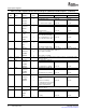
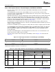
The video capture channel x field 1 start register (VC xSTRT1) is shown in Figure 3-23 and described in
Table 3-16 .
SPRUEM1 – May 2007 Video Capture Port 75
Submit Documentation Feedback