
Video Port/VCXO Interpolated Control (VIC) Port User's Guide


www.ti.com
Video Capture Registers
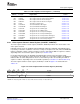
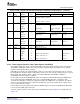
Figure 3-22. Video Capture Channel A Control Register (VCACTL)
31 30 29 24
RSTCH BLKCAP Reserved
R/WS-0 R/W-1 R-0
23 22 21 20 19 18 17 16
Reserved RDFE FINV EXC FLDD VRST HRST
R-0 R/W-0 R/W-0 R/W-0 R/W-0 R/W-1 R/W-0
15 14 13 12 11 10 9 8
VCEN Reserved LFDE SFDE RESMPL Reserved SCALE
R/W-0 R-0 R/W-0 R/W-0 R/W-0 R-0 R/W-0
7 6 5 4 3 2 0
CON FRAME CF2 CF1 Reserved CMODE
R/W-0 R/W-0 R/W-1 R/W-1 R-0 R/W-0
LEGEND: R/W = Read/Write; R = Read only; WS = Write 1 to reset, a write of 0 has no effect; - n = value after reset
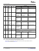
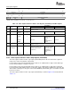
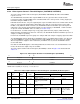
Table 3-15. Video Capture Channel A Control Register (VCACTL) Field Descriptions
Description
Bit field
(1)
symval
(1)
Value BT.656 or Y/C Mode Raw Data Mode TCI Mode
31 RSTCH OF( value) Reset channel bit. Write 1 to reset the bit, a write of 0 has no effect.
DEFAULT 0 No effect.
NONE
RESET 1 Resets the channel by blocking further EDMA event generation and flushing the
FIFO upon completion of any pending EDMAs. Also clears the VCEN bit. All
channel registers are set to their initial values. RSTCH is auto-cleared after
channel reset is complete.
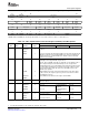
30 BLKCAP OF( value) Block capture events bit. BLKCAP functions as a capture FIFO reset without
affecting the current programmable register values.
The F1C, F2C, and FRMC status bits, in VCASTAT, are not updated. Field or
frame complete interrupts and vertical interrupts are also not generated.
Clearing BLKCAP does not enable EDMA events during the field where the bit
is cleared. Whenever BLKCAP is set and then cleared, the software needs to
clear the field and frame status bits (F1C, F2C, and FRMC) as part of the
BLKCAP clear operation.
CLEAR 0 Enables EDMA events in the video frame that follows the video frame where
the bit is cleared. (The capture logic must sync to the start of the next frame
after BLKCAP is cleared.)
DEFAULT 1 Blocks EDMA events and flushes the capture channel FIFOs.
BLOCK
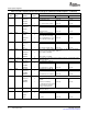
29-22 Reserved - 0 Reserved. The reserved bit location is always read as 0. A value written to this
field has no effect.
21 RDFE OF( value) Field identification enable bit. (Channel A only)
DEFAULT 0 Not used. Field identification is Not used.
disabled.
DISABLE
ENABLE 1 Not used. Field identification is Not used.
enabled.
20 FINV OF( value) Detected field invert bit.
DEFAULT 0 Detected 0 is field 1. Not used. Not used.
FIELD1
FIELD2 1 Detected 0 is field 2. Not used. Not used.
(1)
For CSL implementation, use the notation VP_VCACTL_ field_ symval
SPRUEM1 – May 2007 Video Capture Port 73
Submit Documentation Feedback