
Video Port/VCXO Interpolated Control (VIC) Port User's Guide


www.ti.com
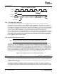
3.9 Capture Line Boundary Conditions
Y FIFO
Cb FIFO
VDOUT[9−2]
VCLKOUT
63 5655 48 47 4039 32
Y 5
Y 4
Y 7 Y 6
Y 69 Y 68
Y 71 Y 70
Y 77 Y 76
Cb 37 Cb 36
Cb 38
Little-Endian Packing
Cb 36 Cb 37 Cb 38 CbDEFCr 36 Cr 37 Cr 38 CrDEF
VDOUT[19−12]
CbDEF CbDEFCrDEF CrDEF
31 24 23 1615 8 7 0
Y 1
Y 0Y 3 Y 2
Y 65 Y 64Y 67 Y 66
Y 73 Y 72Y 75 Y 74
31 24 23 16 15 8 7 0
Cb 33 Cb 32Cb 35 Cb 34
63 5655 48 47 4039 32
IPCOUNT = IMGHSIZE(78)
Cb 5 Cb 4
Cb 7 Cb 6
Cb 1 Cb 0Cb 3 Cb 2
Cr FIFO
Cr 37 Cr 36
Cr 38
31 24 23 16 15 8 7 0
Cr 33 Cr 32Cr 35 Cr 34
63 5655 48 47 4039 32
Cr 5 Cr 4
Cr 7 Cr 6
Cr 1 Cr 0Cr 3 Cr 2
Line n
Line n+1
Line n
Line n+1
Line n
Line n+1
3.10 Capturing Video in BT.656 or Y/C Mode
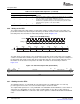
Capture Line Boundary Conditions
The video port generates a YEVT after the specified number of new samples has been captured in the
buffer. The number of samples required to generate YEVT is programmable and is set in the VCTHRLD1
bits of VCATHRLD. VCTHRLD1 should be set to the packet size plus 8 bytes of timestamp. On every
YEVT, the EDMA should move data from the buffer to the DSP memory. When moving data from the
buffer to the DSP memory, the EDMA should use the memory address of the YSRCA location as a source
address.
In order to simplify EDMA transfers, FIFO double words must not contain data from more than one capture
line. This means that a FIFO write must be performed whenever 8 bytes have been received or when the
line complete condition (HCOUNT = VCXSTOP) occurs. Thus, every captured line begins on a double
word boundary and non-double word length lines are padded at the end. An example is shown in
Figure 3-20 .
In Figure 3-20 (8-bit Y/C mode), the line length is not a double word. When the condition HCOUNT =
VCXSTOP occurs, the FIFO location is written even though 8 bytes have not been received. The next
capture line then begins in the next FIFO location at byte 0. This operation extends to all capture modes.
In the case of TCI and raw data modes, there are no lines. In these modes, a final write at the end of the
packet must be performed when the packet data count equals the 24-bit combined value of VCXCOUNT
and VCYCOUNT.
Figure 3-20. Capture Line Boundary Example
In order to capture video in the BT.656 or Y/C format, the following steps are needed:
1. To use the desired Video Port, program the Pin Mux register (PINMUX) appropriately to ensure that
the multiplexed pins work as Video Port Pins. Refer to the device-specific data manual for details about
PINMUX register.
2. Program the VPx_CTL register appropriately to use the desired Video Port as a Capture Port.
3. Set the PEREN bit in the video port peripheral control register (PCR).
4. Set the last pixel to be captured in VC xSTOP1 and VC xSTOP2 (set the VCXSTOP and VCYSTOP
bits).
5. Set the first pixel to be captured in VC xSTRT1 and VC xSTRT2 (set the VCXSTART and VCYSTART
bits).
6. Write to VC xTHRLD to set the capture threshold. The threshold needs to be set in units of double
word. One double word is equal to 8 bytes. Every time the number of received bytes reaches the
SPRUEM1 – May 2007 Video Capture Port 67
Submit Documentation Feedback