
Video Port/VCXO Interpolated Control (VIC) Port User's Guide


www.ti.com
3.7.2 Raw Data FIFO Packing
Raw FIFO
VDIN[9−2] / VDIN[19−12]
VCLKINA / VCLKINB
63 5655 4847 4039 32
Raw 5 Raw 4Raw 7 Raw 6
Raw 13 Raw 12Raw 15 Raw 14
Little-Endian Packing
31 2423 1615 8 7 0
Raw 1 Raw 0Raw 3 Raw 2
Raw 9 Raw 8Raw 11 Raw 10
Raw Data Capture Mode
For channel B operation or when the RDFE bit in VCACTL is not set, no field information is available.
Some flexibility in capture and DSP notification is still provided in order to accommodate various EDMA
structures and processing flows. Each raw data packet is treated similar to a progressive scan video
frame. The raw data mode uses the CON and FRAME bits of VC xCTL in a slightly different manner, as
listed in Table 3-11 .
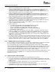
Table 3-11. Raw Data Mode Capture Operation
VC xCTL Bit
CON FRAME CF2 CF1 Operation
0 0 x x Noncontinuous frame capture. FRMC is set after data block capture and
causes CCMPx to be set. Capture will halt upon completion of the next frame
unless the FRMC bit is cleared. (DSP has the entire next frame time to clear
FRMC.)
0 1 x x Single frame capture. FRMC is set after data block capture and causes
CCMPx to be set. Capture is halted until the FRMC bit is cleared.
1 0 x x Continuous frame capture. FRMC is set after data block capture and causes
CCMPx to be set (CCMPx interrupt can be disabled). The port will continue
capturing frames regardless of the state of FRMC.
1 1 x x Reserved
The CON bit controls the capture of multiple frames. When CON = 1, continuous capture is enabled, the
video port captures incoming frames (assuming the VCEN bit is set) without the need for DSP interaction.
It relies on a EDMA structure with circular buffering capability to service the capture FIFO. When CON = 0,
continuous capture is disabled, the video port sets the frame capture complete bit (FRMC) in VC xSTAT
upon the capture of each frame. Once the capture complete bit is set, at most, one more frame can be
received before capture operation is halted (as determined by the FRAME bit state). This prevents
subsequent data from overwriting previous frames until the DSP has a chance to update EDMA pointers
or process those fields.
Captured data is always packed into 64-bits before being written into the capture FIFO(s). By default, data
is packed into the FIFO from right to left.
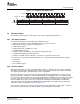
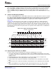
The 8-bit raw-data mode stores all data in a single FIFO. Samples are packed together as shown in
Figure 3-13 .
Figure 3-13. 8-Bit Raw Data FIFO Packing
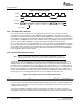
The 16-bit raw data mode stores all data into a single FIFO. Samples are packed together as shown in
Figure 3-14 .
62 Video Capture Port SPRUEM1 – May 2007
Submit Documentation Feedback