
Video Port/VCXO Interpolated Control (VIC) Port User's Guide

www.ti.com
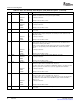
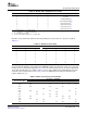
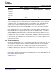
3.2.3 BT.656 Image Window and Capture
Capture Image
Ystart
Xstart
Ystop
Xstop
Field 1
Capture Image
Ystart
Xstart
Ystop
Xstop
Field 2
Hcount=0
Ycount=1
Ycount=1
BT.656 Video Capture Mode
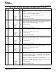
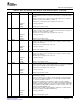
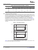
Table 3-4. Error Correction by Protection Bits (continued)
Received F, V, and H Bits
Received P
3
-P
0
Bits 000 001 010 011 100 101 110 111
1011 010 - 010 010 - 101 010 -
1100 - 001 110 - 110 - 110 110
1101 001 001 - 001 - 001 110 -
1110 - - - 011 - 101 110 -
1111 - 001 010 - 100 - - -
The BT.656 format is an interlaced format consisting of two fields. The video port allows capture of one or
both fields. The captured image is a subset of each field and can be larger or smaller than the active video
region. The captured image position is defined by the VC xSTRT1 and VC xSTOP1 registers for field 1, and
the VC xSTRT2 and VC xSTOP2 registers for field 2. The VCXSTART and VCXSTOP bits set the
horizontal window position for the field relative to the HCOUNT pixel counter. The VCYSTART and
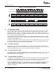
VCYSTOP bits set the vertical position relative to the VCOUNT line counter. This is shown in Figure 3-1 .
HCOUNT increments on every chroma sample period (every other VCLKIN rising edge) for which capture
is enabled. Once VCOUNT = YSTART, line capture begins when HCOUNT = XSTART. It continues until
HCOUNT = XSTOP. A field's capture is complete when HCOUNT = VCXSTOP and VCOUNT =
VCYSTOP.
Figure 3-1. Video Capture Parameters
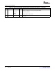
Table 3-5 shows common digital camera standards and the number of fields per second, number of active
lines per field, and the number of active pixels per line.
48 Video Capture Port SPRUEM1 – May 2007
Submit Documentation Feedback