
Video Port/VCXO Interpolated Control (VIC) Port User's Guide

www.ti.com
Video Port Control Registers
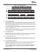
Table 2-6. Video Port Interrupt Status Register (VPIS) Field Descriptions (continued)
Bit field
(1)
symval
(1)
Value Description
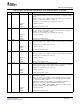
7 LFDA OF( value) Long field detected on channel A interrupt detected bit. (A long field is only detected
when the VRST bit in VCACTL is cleared to 0; when VRST = 1, a long field is always
detected.)
BT.656 or Y/C capture mode - LFDA is set when long field detection is enabled and
VCOUNT is not reset before VCOUNT = YSTOP + 1.
Raw data mode, or TCI capture mode or display mode - Not used.
DEFAULT 0 No interrupt is detected.
NONE
CLEAR 1 Interrupt is detected. Bit is cleared.
6 SFDA OF( value) Short field detected on channel A interrupt detected bit.
BT.656 or Y/C capture mode - SFDA is set when short field detection is enabled and
VCOUNT is reset before VCOUNT = YSTOP.
Raw data mode, or TCI capture mode or display mode - Not used.
DEFAULT 0 No interrupt is detected.
NONE
CLEAR 1 Interrupt is detected. Bit is cleared.
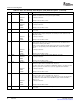
5 VINTA2 OF( value) Channel A field 2 vertical interrupt detected bit.
BT.656, or Y/C capture mode or any display mode - VINTA2 is set when a vertical
interrupt occurred in field 2.
Raw data mode or TCI capture mode - Not used.
DEFAULT 0 No interrupt is detected.
NONE
CLEAR 1 Interrupt is detected. Bit is cleared.
4 VINTA1 OF( value) Channel A field 1 vertical interrupt detected bit.
BT.656, or Y/C capture mode or any display mode - VINTA1 is set when a vertical
interrupt occurred in field 1.
Raw data mode or TCI capture mode - Not used.
DEFAULT 0 No interrupt is detected.
NONE
CLEAR 1 Interrupt is detected. Bit is cleared.
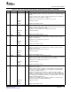
3 SERRA OF( value) Channel A synchronization error interrupt detected bit.
BT.656 or Y/C capture mode - Synchronization parity error on channel A. An SERRA
typically requires resetting the channel (RSTCH) or the port (VPRST).
Raw data mode or TCI capture mode - Not used.
DEFAULT 0 No interrupt is detected.
NONE
CLEAR 1 Interrupt is detected. Bit is cleared.
2 CCMPA OF( value) Capture complete on channel A interrupt detected bit. (Data is not in memory until the
EDMA transfer is complete.)
BT.656 or Y/C capture mode - CCMPA is set after capturing an entire field or frame
(when F1C, F2C, or FRMC in VCASTAT are set) depending on the CON, FRAME,
CF1, and CF2 control bits in VCACTL.
Raw data mode - If RDFE bit is set, CCMPA is set when F1C, F2C, or FRMC in
VCASTAT is set (when the data counter = the combined VCYSTOP/VCXSTOP value)
depending on the CON, FRAME, CF1, and CF2 control bits in VCACTL. If RDFE bit is
not set, CCMPA is set when FRMC in VCASTAT is set (when the data counter = the
combined VCYSTOP/VCXSTOP value)
TCI capture mode - CCMPA is set when FRMC in VCASTAT is set (when the data
counter = the combined VCYSTOP/VCXSTOP value).
DEFAULT 0 No interrupt is detected.
NONE
CLEAR 1 Interrupt is detected. Bit is cleared.
SPRUEM1 – May 2007 Video Port 43
Submit Documentation Feedback