
Video Port/VCXO Interpolated Control (VIC) Port User's Guide


www.ti.com
1.2.2 Video Capture FIFO Configurations
VDIN[9−2]
VDIN[19−12]
Capture FIFO A
Y Buffer A (1280 bytes)
Cb Buffer A (640 bytes)
8
8
64
64
Cb Buffer B (640 bytes)
Cr Buffer B (640 bytes)
CRSRCB
CBSRCB
8
8
8
8
CBSRCA
64
64
64
Capture FIFO B
Cr Buffer A (640 bytes)
YSRCB
CRSRCA
64
YSRCA
Y Buffer B (1280 bytes)
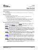
Video Port FIFO
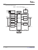
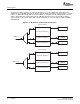
During video capture operation, the video port FIFO has one of four configurations depending on the
capture mode. For BT.656 operation, the FIFO is split into channel A and B, as shown in Figure 1-2 . Each
FIFO is clocked independently with the channel A FIFO receiving data from the VDIN[9-2] half of the bus
and the channel B FIFO receiving data from the VDIN[19-12] half of the bus. Each channel's FIFO is
further split into Y, Cb, and Cr buffers with separate write pointers and read registers (YSRC x, CBSRC x,
and CRSRC x).
Figure 1-2. BT.656 Video Capture FIFO Configuration
20 Overview SPRUEM1 – May 2007
Submit Documentation Feedback