
Video Port/VCXO Interpolated Control (VIC) Port User's Guide


www.ti.com
6.4 Enabling VIC Port
6.5 VIC Port Registers
Enabling VIC Port
Perform the following steps to enable the VIC port.
1. Clear the GO bit in the VIC control register (VICCTL) to 0.
2. Set the PRECISION bits in VICCTL to the desired precision.
3. Set the VIC clock divider register (VICDIV) bits to appropriate value based on the precision and
interpolation frequency.
4. Set the GO bit in VICCTL to 1.
5. The VIC input register (VICIN) is written into every time a new input code is available for interpolation.
Repeat step Step 1 as often as needed.
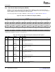
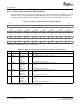
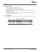
The VIC port registers are listed in Table 6-3 . See the device-specific datasheet for the memory address
of these registers.
Table 6-3. VIC Port Registers
Offset
Address
(1)
Acronym Register Name Section
00h VICCTL VIC Control Register Section 6.5.1
04h VICIN VIC Input Register Section 6.5.2
08h VICDIV VIC Clock Divider Register Section 6.5.3
(1)
The absolute address of the registers is device specific and is equal to the base address + offset
address. See the device-specific datasheet to verify the register addresses.
VCXO Interpolated Control Port170 SPRUEM1 – May 2007
Submit Documentation Feedback