
Video Port/VCXO Interpolated Control (VIC) Port User's Guide


www.ti.com
4.12.26 Video Display Field Bit Register (VDFBIT)
Video Display Registers
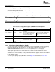
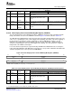
Figure 4-56. Video Display Vertical Interrupt Register (VDVINT)
31 30 28 27 16
VIF2 Reserved VINT2
R/W-0 R-0 R/W-0
15 14 12 11 0
VIF1 Reserved VINT1
R/W-0 R-0 R/W-0
LEGEND: R/W = Read/Write; R = Read only; - n = value after reset
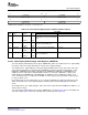
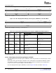
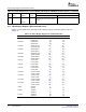
Table 4-30. Video Display Vertical Interrupt Register (VDVINT) Field Descriptions
Bit field
(1)
symval
(1)
Value Description
31 VIF2 OF( value) Vertical interrupt (VINT) in field 2 enable bit.
DEFAULT 0 Vertical interrupt (VINT) in field 2 is disabled.
DISABLE
ENABLE 1 Vertical interrupt (VINT) in field 2 is enabled.
30-28 Reserved - 0 Reserved. The reserved bit location is always read as 0. A value written to this field
has no effect.
27-16 VINT2 OF( value) 0-FFFh Line where vertical interrupt (VINT) occurs, if VIF2 bit is set.
DEFAULT 0
15 VIF1 OF( value) Vertical interrupt (VINT) in field 1 enable bit.
DEFAULT 0 Vertical interrupt (VINT) in field 1 is disabled.
DISABLE
ENABLE 1 Vertical interrupt (VINT) in field 1 is enabled.
14-12 Reserved - 0 Reserved. The reserved bit location is always read as 0. A value written to this field
has no effect.
11-0 VINT1 OF( value) 0-FFFh Line where vertical interrupt (VINT) occurs, if VIF1 bit is set.
DEFAULT 0
(1)
For CSL implementation, use the notation VP_VDVINT_ field_ symval
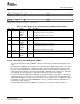
The video display field bit register (VDFBIT) controls the F bit value in the EAV and SAV timing control
codes.
The FBITCLR and FBITSET bits control the F bit value in the EAV and SAV timing control codes. The F
bit is cleared to 0 (indicating field 1 display) in the EAV code at the beginning of the line whenever the
frame line counter (FLCOUNT) is equal to FBITCLR. It remains a 0 for all subsequent EAV/SAV codes
until the EAV at the beginning of the line when FLCOUNT = FBITSET where it changes to 1 (indicating
field 2 display). The F bit operation is completely independent of the FLD control signal.
For interlaced operation, FBITCLR and FBITSET are typically programmed such that the F bit changes
coincidently with or some time after the V bit transitions from 1 to 0 (as determined by VBITCLR1 and
VBITCLR2 in VDVBIT n). For progressive scan operation no field 2 output occurs, so FBITSET should be
programmed to a value greater than FRMHEIGHT so that the condition FLCOUNT = FBITSET never
occurs and the F bit is always 0.
The video display field bit register (VDFBIT) is shown in Figure 4-57 and described in Table 4-31 .
SPRUEM1 – May 2007 Video Display Port 145
Submit Documentation Feedback