
Video Port/VCXO Interpolated Control (VIC) Port User's Guide


www.ti.com
720 721 722 723 735 736 799 800 855 856 857 0 1 7 8 9 10 710 711 712 718 719 720 721
703 703 703 703 703 703 703 703
703 703 703
703
0 1 2
702 703 703703 703 703 703
n + 1
n
FLCOUNT
VCLKOUT
VCTL1 (HBLNK
)(A)(C)
IPCOUNT
FPCOUNT
VCLKIN
VCTL1 (HSYNC)
(A)(C)
VDOUT[9−2]
n − 1
4
268
4
1440
One Line Next
Line
(B)
Blanking Active Video
Display
Image
EAV Blanking Data SAV EAV
703703
Def
Cr
Def
Y
FF.C
00.0
00.0
XY.0
80.0
10.0
10.0
80.0
80.0
10.0
10.0
80.0
FF.C
00.0
00.0
XY.0
Def
Cb
Def
Y
Def
Cr
Def
Y
Def
Cr
Def
Y
Cb0
Y0
Cr0
Y1
Cb1
Y2
Cb351
Y702
Cr351
Y703
Def
Cb
Def
Y
Def
Cb
Def
Y
Def
Cr
Def
Y
FF.C
00.0
00.0
XY.0
FRMWIDTH = 858 IMGHOFF1 = 8 HSYNCSTART = 736
HBLNKSTART = 720 IMGHSIZE1 = 704 HSYNCSTOP = 800
HBLNKSTOP = 856 IMGHOFF2 = 8
IMGHSIZE2 = 704
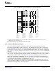
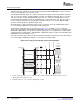
Display Timing Examples
Figure 4-25. BT.656 Interlaced Display Horizontal Timing Example
A Assumes VCT0P bit in VPCTL is set to 1 (active-low output). HSYNC output when VCTL1S bit in VDCTL is set to 00, HBLNK output when VCTL1S bit is set 01.
B HBLNK operation when HBDLA bit in VDHBLNK is set to 1.
C Diagram assumes a two VCLK pipeline delay between internal counters and output signals.
SPRUEM1 – May 2007 Video Display Port 111
Submit Documentation Feedback