
TMS320DM644x DMSoC Multimedia Card (MMC)/Secure Digital (SD) Card Controller User's Guide

www.ti.com
4.1 MMC Control Register (MMCCTL)
Registers
The MMC control register (MMCCTL) is used to enable or configure various modes of the MMC controller.
Set or clear the DATRST and CMDRST bits at the same time to reset or enable the MMC controller.
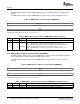
The MMC control register (MMCCTL) is shown in Figure 18 and described in Table 6 .
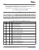
Figure 18. MMC Control Register (MMCCTL)
31 16
Reserved
R-0
15 11 10 9 8
Reserved PERMDX PERMDR Reserved
R-0 R/W-0 R/W-0 R-0
7 6 5 3 2 1 0
DATEG Reserved WIDTH CMDRST DATRST
R/W-0 R-0 R/W-0 R/W-0 R/W-0
LEGEND: R/W = Read/Write; R = Read only; - n = value after reset
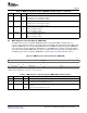
Table 6. MMC Control Register (MMCCTL) Field Descriptions
Bit Field Value Description
31-11 Reserved 0 Reserved
10 PERMDX Endian select when writing.
0 Little endian is selected.
1 Big endian is selected.
9 PERMDR Endian select when reading.
0 Little endian is selected.
1 Big endian is selected.
8 Reserved 0 Reserved
7-6 DATEG 0-3h DAT3 edge detection select.
0 DAT3 edge detection is disabled.
1h DAT3 rising-edge detection is enabled.
2h DAT3 falling-edge detection is enabled.
3h DAT3 rising-edge and falling-edge detections are enabled.
5-3 Reserved 0 Reserved
2 WIDTH Data bus width (MMC mode only).
0 Data bus has 1 bit (only DAT0 is used).
1 Data bus has 4 bits (all DAT0-3 are used).
1 CMDRST CMD logic reset.
0 CMD line portion is enabled.
1 CMD line portion is disabled and in reset state.
0 DATRST DAT logic reset.
0 DAT line portion is enabled.
1 DAT line portion is disabled and in reset state.
SPRUE30B – September 2006 Multimedia Card (MMC)/Secure Digital (SD) Card Controller 41
Submit Documentation Feedback