
TMS320DM644x DMSoC Multimedia Card (MMC)/Secure Digital (SD) Card Controller User's Guide

www.ti.com
2.2 Signal Descriptions
2.3 Protocol Descriptions
2.3.1 MMC/SD Mode Write Sequence
Peripheral Architecture
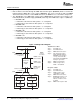
Table 1 shows the MMC/SD controller pins that each mode uses. The MMC/SD protocol uses the clock,
command (two-way communication between the MMC controller and memory card), and data (DAT0 for
MMC card, DAT0-3 for SD card) pins.
Table 1. MMC/SD Controller Pins Used in Each Mode
Function
MMC and SD (1-bit mode) SD (4-bit mode)
Pin Type
(1)
Communications Communications
CLK O Clock line Clock line
CMD I/O Command line Command line
DAT0 I/O Data line 0 Data line 0
DAT1 I/O (Not used) Data line 1
DAT2 I/O (Not used) Data line 2
DAT3 I/O (Not used) Data line 3
(1)
I = input to the MMC controller; O = output from the MMC controller.
The MMC/SD controller follows the MMC/SD protocol for completing any kind of transaction with the
multimedia card and secure digital cards. For more detailed information, refer to the supported MMC and
SD specifications in Section 1.5 .
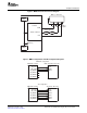
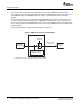
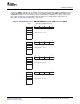
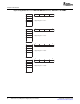
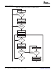
Figure 5 and Table 2 show the signal activity when the MMC/SD controller is in the MMC/SD mode and is
writing data to a memory card. The same block length must be defined in the MMC/SD controller and in
the memory card before initiating a data write. In a successful write protocol sequence, the following steps
occur:
• The MMC/SD controller requests the CSD content.
• The card receives the command and sends the content of the CSD register as its response.
• If the desired block length, WRITE_BL_LEN value, is different from the default value determined from
the response, the MMC/SD controller sends the block length command.
• The card receives the command and sends responses to the command.
• The MMC/SD controller requests the card to change states from standby to transfer.
• The card receives the command and sends responses to the command.
• The MMC/SD controller sends a write command to the card.
• The card receives the command and sends responses to the command.
• The MMC/SD controller sends a block of data to the card.
• The card sends the CRC status to the MMC/SD controller.
• The card sends a low BUSY bit until all of the data has been programmed into the flash memory inside
the card.
SPRUE30B – September 2006 Multimedia Card (MMC)/Secure Digital (SD) Card Controller 13
Submit Documentation Feedback