
DSP Subsystem Reference Guide


www.ti.com
9.6.2 EDMA Transfer Controller Configuration
9.7 Boot Control
Boot Control
Each switched central resource (SCR) performs prioritization based on the priority level of the master that
sends the command. Each bus master's priority is programmed in the chip-level Bus Master Priority
Control Registers (MSTPRI0 or MSTPRI1). The default priority level for each bus master is shown in
Table 9-2 . Application software is expected to modify these values to obtain the desired system
performance.
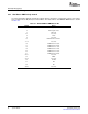
Table 9-2. TMS320DM643x DMP Default Master Priorities
Master Default Priority
VPSS 0
(1)
EDMA Ch 0 0
(2)
EDMA Ch 1 0
(2)
EDMA Ch 2 0
(2)
DSP (DMA) 7
(3)
DSP (CFG) 1
EMAC 4
VLYNQ 4
PCI 4
(1)
Default value in VPSS PCR register
(2)
Default value in EDMA QUEPRI register
(3)
Default value in DSP MDMAARBE.PRI field
The EDMA transfer controller default burst size configuration register (EDMATCCFG) in the System
module configures the default burst size for the EDMA transfer controllers (EDMATC0, EDMATC1, and
EDMATC2). Refer to the device-specific data manual for more information on this register.
The System Module contains the following boot control registers:
• Device Boot Configuration Register (BOOTCFG)
• Boot Complete Register (BOOTCMPLT)
• DSP Boot Address Register (DSPBOOTADDR)
See Chapter 11 and the device-specific data manual for descriptions of these registers.
SPRU978E – March 2008 System Module 89
Submit Documentation Feedback