
DSP Subsystem Reference Guide

www.ti.com
6.2 Power Domain and Module Topology
Power Domain and Module Topology
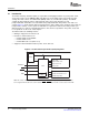
The DM643x DMP includes one power domain--the AlwaysOn power domain. The AlwaysOn power
domain is always on when the chip is on. The AlwaysOn domain is powered by the V
DD
pins of the
DM643x DMP (see the device-specific data manual). All of the DM643x DMP modules reside within the
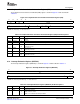
AlwaysOn power domain. Table 6-1 lists all the possible peripherals on the DM643x DMP, their LPSC
assignments, and default module states. Refer to the device-specific data manual for the peripherals
available on a given device. The module states are defined in Section 6.3.2 .
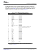
Table 6-1. DM643x DMP Default Module Configuration
LPSC
Number Module Name Default Module State (MDSTAT.STATE)
0 VPSS (master) SwRstDisable
1 VPSS (slave) SwRstDisable
2 EDMACC SwRstDisable
3 EDMATC0 SwRstDisable
4 EDMATC1 SwRstDisable
5 EDMATC2 SwRstDisable
6 EMAC Memory Controller SwRstDisable
7 MDIO SwRstDisable
8 EMAC SwRstDisable
9 McASP0 SwRstDisable
10 Reserved -
11 VLYNQ SwRstDisable
12 HPI SwRstDisable
13 DDR2 Memory Controller SwRstDisable
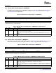
14 EMIFA SwRstDisable, if configuration pins AEM[2:0] = 000b
Enable, if configuration pins AEM[2:0] = others
15 PCI SwRstDisable
16 McBSP0 SwRstDisable
17 McBSP1 SwRstDisable
18 I2C SwRstDisable
19 UART0 SwRstDisable
20 UART1 SwRstDisable
21 Reserved SwRstDisable
(1)
22 HECC SwRstDisable
23 PWM0 SwRstDisable
24 PWM1 SwRstDisable
25 PWM2 SwRstDisable
26 GPIO SwRstDisable
27 TIMER0 SwRstDisable
28 TIMER1 SwRstDisable
29-38 Reserved -
39 C64x+ CPU Enable
40 Reserved -
(1)
For this reserved domain, it is important not to set the corresponding STATE bits in the module
status n registers (MDSTAT0-MDSTAT39) to disable. For more details on MDSTAT n and the
STATE bits, see Section 6.7.9 .
SPRU978E – March 2008 Power and Sleep Controller 63
Submit Documentation Feedback