
DSP Subsystem Reference Guide

www.ti.com
5.4.1 Peripheral ID Register (PID)
5.4.2 Reset Type Status Register (RSTYPE)
PLL Controller Registers
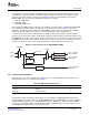
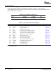
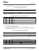
The peripheral ID register (PID) is shown in Figure 5-3 and described in Table 5-5 .
Figure 5-3. Peripheral ID Register (PID)
31 24 23 16
Reserved TYPE
R-0 R-1h
15 8 7 0
CLASS REV
R-8h R-Dh
LEGEND: R = Read only; - n = value after reset
Table 5-5. Peripheral ID Register (PID) Field Descriptions
Bit Field Value Description
31-24 Reserved 0 Reserved
23-16 TYPE Peripheral type
1h PLLC
15-8 CLASS Peripheral class
8h Current class
7-0 REV Peripheral revision
Dh Current revision
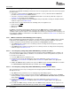
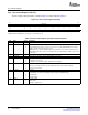
The reset type status register (RSTYPE) is shown in Figure 5-4 and described in Table 5-6 . It latches
cause of the last reset. Although the reset value of all bits is 0 after coming out of reset, one bit is set to 1
to indicate the cause of the reset.
Figure 5-4. Reset Type Status Register (RSTYPE)
31 16
Reserved
R-0
15 3 2 1 0
Reserved MRST XWRST POR
R-0 R-0 R-0 R-0
LEGEND: R = Read only; - n = value after reset
Table 5-6. Reset Type Status Register (RSTYPE) Field Descriptions
Bit Field Value Description
31-3 Reserved 0 Reserved
2 MRST 0-1 Maximum reset. If 1, maximum reset was the reset to occur that is of highest priority.
1 XWRST 0-1 External warm reset. If 1, warm reset ( RESET) was the last reset to occur that is of highest priority.
0 POR 0-1 Power on reset. If 1, power on reset ( POR) was the last reset to occur that is of highest priority.
SPRU978E – March 2008 PLL Controller 49
Submit Documentation Feedback