
Universal Serial Bus Controller User's Guide

4.23 Receive CPPI Raw Status Register (RCPPIRAWSR)
4.24 Receive CPPI Interrupt Enable Set Register (RCPPIENSETR)
Registers
www.ti.com
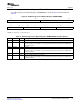
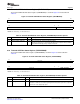
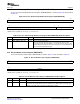
The Receive CPPI Raw Status Register (RCPPIRAWSR) is shown in Figure 38 and described in
Table 39 .
Figure 38. Receive CPPI Raw Status Register (RCPPIRAWSR)
31 16
Reserved
R-0
15 4 3 0
Reserved COMP_PENDING
R-0 R-0
LEGEND: R = Read only; - n = value after reset
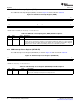
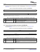
Table 39. Receive CPPI Raw Status Register (RCPPIRAWSR) Field Descriptions
Bit Field Value Description
31-4 Reserved 0 Reserved
3-0 COMP_PENDING 0-Fh Raw Receive Completion Pending
Indicators for channels 3 to 0 Active high flags which indicate that a packet has completed
reception
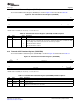
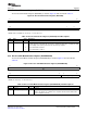
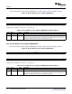
The Receive CPPI Interrupt Enable Set Register (RCPPIENSETR) is shown in Figure 39 and described in
Table 40 .
Figure 39. Receive CPPI Interrupt Enable Set Register (RCPPIENSETR)
31 16
Reserved
R-0
15 4 3 0
Reserved COMP_PENDING_INTR_EN
R-0 R/W-0
LEGEND: R/W = Read/Write; R = Read only; - n = value after reset
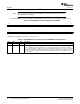
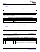
Table 40. Receive CPPI Interrupt Enable Set Register (RCPPIENSETR) Field Descriptions
Bit Field Value Description
31-4 Reserved 0 Reserved
3-0 COMP_PENDING_INTR_EN 0-Fh Receive CPPI Interrupt Enables
These are active high interrupt enables corresponding to the Receive CPPI Completion
Pending status bits. Writing a 1 to any of the bits in the Receive CPPI Interrupt Enable
Set Register will result in setting of the corresponding bit in the Receive CPPI Interrupt
Enable Register.
98 Universal Serial Bus (USB) Controller SPRUGH3 – November 2008
Submit Documentation Feedback