
Universal Serial Bus Controller User's Guide

4.12 USB End of Interrupt Register (EOIR)
4.13 USB Interrupt Vector Register (INTVECTR)
Registers
www.ti.com
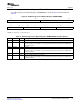
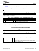
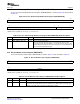
The USB End of Interrupt Register (EOIR) is shown in Figure 27 and described in Table 28 .
Figure 27. USB End of Interrupt Register (EOIR)
31 16
Reserved
R-0
15 8 7 0
Reserved VECTOR
R-0 R/W-0
LEGEND: R/W = Read/Write; R = Read only; - n = value after reset
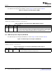
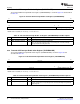
Table 28. USB End of Interrupt Register (EOIR) Field Descriptions
Bit Field Value Description
31-8 Reserved 0 Reserved
7-0 VECTOR 0-FFh EOI Vector
Allows the CPU to acknowledge completion of an interrupt by writing to the EOI. An eoi_write signal will
be generated, the EOI vector will be updated to the written value, and another interrupt will be triggered
if interrupt sources remain. Software should always write zeros for the EOI vector value.
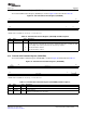
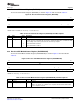
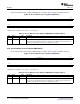
The USB Interrupt Vector Register (INTVECTR) is shown in Figure 28 and described in Table 29 .
Figure 28. USB Interrupt Vector Register (INTVECTR)
31 0
VECTOR
R-0
LEGEND: R = Read only; - n = value after reset
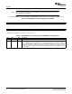
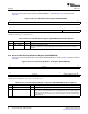
Table 29. USB Interrupt Vector Register (INTVECTR) Field Descriptions
Bit Field Value Description
31-0 VECTOR 0-FFFF FFFFh Input Interrupt Vector
Recycles the Interrupt Vector input to be read by the CPU
Universal Serial Bus (USB) Controller92 SPRUGH3 – November 2008
Submit Documentation Feedback