
Universal Serial Bus Controller User's Guide
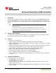
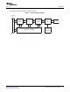
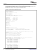

1.4 Functional Block Diagram
Internal
bus
CPPI
DMA
engine
FIFO encode/
decode
Packet USB
PHY
2.0
USB
24 MHz
oscillator
crystal
Registers, interrupts, endpoint control,
and packet scheduling
www.ti.com
Introduction
The USB functional block diagram is shown in Figure 1 .
Figure 1. Functional Block Diagram
SPRUGH3 – November 2008 Universal Serial Bus (USB) Controller 15
Submit Documentation Feedback