
Universal Serial Bus Controller User's Guide

4.49 Interrupt Enable Register for INTRTX (INTRTXE)
4.50 Interrupt Enable Register for INTRRX (INTRRXE)
www.ti.com
Registers
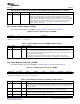
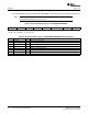
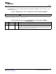
Figure 63. Interrupt Register for Receive Endpoints 1 to 4 (INTRRX)
31 16
Reserved
R-0
15 5 4 3 2 1 0
Reserved EP4RX EP3RX EP2RX EP1RX Reserved
R-0 R-0 R-0 R-0 R-0 R-0
LEGEND: R = Read only; - n = value after reset
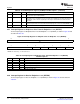
Table 64. Interrupt Register for Receive Endpoints 1 to 4 (INTRRX) Field Descriptions
Bit Field Value Description
15-5 Reserved 0 Reserved
4 EP4RX 0-1 Receive Endpoint 4 interrupt active
3 EP3RX 0-1 Receive Endpoint 3 interrupt active
2 EP2RX 0-1 Receive Endpoint 2 interrupt active
1 EP1RX 0-1 Receive Endpoint 1 interrupt active
0 Reserved 0 Reserved
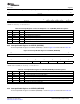
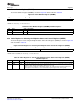
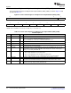
The Interrupt Enable Register for INTRTX (INTRTXE) is shown in Figure 64 and described in Table 65 .
Figure 64. Interrupt Enable Register for INTRTX (INTRTXE)
15 8
Reserved
R-0
7 5 4 3 2 1 0
Reserved EP4TX EP3TX EP2TX EP1TX EP0
R-0 R/W-1 R/W-1 R/W-1 R/W-1 R/W-1
LEGEND: R/W = Read/Write; R = Read only; - n = value after reset
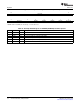
Table 65. Interrupt Enable Register for INTRTX (INTRTXE) Field Descriptions
Bit Field Value Description
15-5 Reserved 0 Reserved
4 EP4TX 0-1 1/0 = Transmit Endpoint 4 interrupt enable/disable
3 EP3TX 0-1 1/0 = Transmit Endpoint 3 interrupt enable/disable
2 EP2TX 0-1 1/0 = Transmit Endpoint 2 interrupt enable/disable
1 EP1TX 0-1 1/0 = Transmit Endpoint 1 interrupt enable/disable
0 EP0 0-1 1/0 = Endpoint 0 interrupt enable/disable
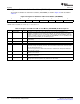
The Interrupt Enable Register for INTRRX (INTRRXE) is shown in Figure 65 and described in Table 66 .
SPRUGH3 – November 2008 Universal Serial Bus (USB) Controller 113
Submit Documentation Feedback