
Universal Serial Bus Controller User's Guide

4.47 Interrupt Register for Endpoint 0 Plus Transmit Endpoints 1 to 4 (INTRTX)
4.48 Interrupt Register for Receive Endpoints 1 to 4 (INTRRX)
Registers
www.ti.com
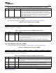
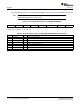
Table 62. Power Management Register (POWER) Field Descriptions (continued)
Bit Field Value Description
3 RESET 0-1 This bit is set when Reset signaling is present on the bus. Note: This bit is Read/Write in Host
Mode, but read-only in Peripheral Mode.
2 RESUME 0-1 Set to generate Resume signaling when the controller is in Suspend mode. The bit should be
cleared after 10 ms (a maximum of 15 ms) to end Resume signaling. In Host mode, this bit is also
automatically set when Resume signaling from the target is detected while the USB controller is
suspended.
1 SUSPENDM 0-1 In Host mode, this bit should be set to enter Suspend mode. In Peripheral mode, this bit is set on
entry into Suspend mode. It is cleared when the interrupt register is read, or the RESUME bit is set.
0 ENSUSPM 0-1 Set to enable the SUSPENDM output.
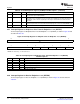
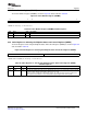
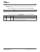
The Interrupt Register for Endpoint 0 Plus Transmit Endpoints 1 to 4 (INTRTX) is shown in Figure 62 and
described in Table 63 .
Figure 62. Interrupt Register for Endpoint 0 Plus Tx Endpoints 1 to 4 (INTRTX)
15 8
Reserved
R-0
7 5 4 3 2 1 0
Reserved EP4TX EP3TX EP2TX EP1TX EP0
R-0 R-0 R-0 R-0 R-0 R-0
LEGEND: R = Read only; - n = value after reset
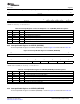
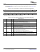
Table 63. Interrupt Register for Endpoint 0 Plus Transmit Endpoints 1 to 4 (INTRTX)
Field Descriptions
Bit Field Value Description
15-5 Reserved 0 Reserved
4 EP4TX 0-1 Transmit Endpoint 4 interrupt active
3 EP3TX 0-1 Transmit Endpoint 3 interrupt active
2 EP2TX 0-1 Transmit Endpoint 2 interrupt active
1 EP1TX 0-1 Transmit Endpoint 1 interrupt active
0 EP0 0-1 Endpoint 0 interrupt active
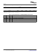
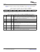
The Interrupt Register for Receive Endpoints 1 to 4 (INTRRX) is shown in Figure 63 and described in
Table 64 .
Universal Serial Bus (USB) Controller112 SPRUGH3 – November 2008
Submit Documentation Feedback