
Digital Media System-on-Chip (DMSoC) Product Preview


www.ti.com
PRODUCT PREVIEW
3.11.4 ARM Boot Mode Configuration
3.11.5 AEMIF Configuration
3.12 Device Boot Modes
TMS320DM355
Digital Media System-on-Chip (DMSoC)
SPRS463A – SEPTEMBER 2007 – REVISED SEPTEMBER 2007
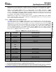
Table 3-16. Module Configuration (continued)
Default States
31 ARM AlwaysOn ON Enable
32 BUS AlwaysOn ON Enable
33 BUS AlwaysOn ON Enable
34 BUS AlwaysOn ON Enable
35 BUS AlwaysOn ON Enable
36 BUS AlwaysOn ON Enable
37 BUS AlwaysOn ON Enable
38 BUS AlwaysOn ON Enable
39 Reserved Reserved Reserved Reserved
40 VPSS DAC Always On ON SyncRst
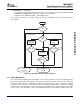
The input pins BTSEL[1:0] determine whether the ARM will boot from its ROM or from the Asynchronous
EMIF (AEMIF). When ROM boot is selected (BTSEL[1:0] = 00, 10, or 11), a jump to the start of internal
ROM (address 0x0000: 8000) is forced into the first fetched instruction word. The embedded ROM boot
loader code (RBL) then performs certain configuration steps, reads the BOOTCFG register to determine
the desired boot method, and branches to the appropriate boot routine (i.e., a NAND, MMC/SD, or UART
loader routine).
If AEMIF boot is selected (BTSEL[1:0] = 01), a jump to the start of AEMIF (address 0x0200: 0000) is
forced into the first fetched instruction word. The ARM then continues executing from external
asynchronous memory using the default AEMIF timings until modified by software.
NOTE
For AEMIF boot, the OneNAND must be connected to the first AEMIF chip select space
(EM_CE0). Also, the AEMIF does not support direct execution from NAND Flash.
Boot modes are further described in Section 3.12 .
3.11.5.1 AEMIF Pin Configuration
The input pins AECFG[3:0] determine the AEMIF configuration immediately after reset. Use AECFG[3:0]
to properly configure the pins of the AEMIF. Refer to the section on pin multiplexing in Section 3.9 .
Also, see the Asynchronous External Memory Interface (AEMIF) Peripheral Reference Guide (SPRUEE8)
for more information on the AEMIF.
3.11.5.2 AEMIF Timing Configuration
When AEMIF is enabled, the wait state registers are reset to the slowest possible configuration, which is
88 cycles per access (16 cycles of setup, 64 cycles of strobe, and 8 cycles of hold). Thus, with a 24 MHz
clock at MXI, the AEMIF is configured to run at 6 MHz/88 which equals approximately 68 kHz by default.
See the Asynchronous External Memory Interface (AEMIF) Peripheral Reference Guide for more
information on the AEMIF.
The DM355 ARM can boot from either Async EMIF (AEMIF/OneNand) or from ARM ROM, as determined
by the setting of the device configuration pins BTSEL[1:0]. The BTSEL[1:0] pins can define the ROM boot
mode further as well.
Submit Documentation Feedback Detailed Device Description 83