
Digital Media System-on-Chip (DMSoC) Product Preview


www.ti.com
PRODUCT PREVIEW
3.11 Default Device Configurations
3.11.1 Device Configuration Pins
TMS320DM355
Digital Media System-on-Chip (DMSoC)
SPRS463A – SEPTEMBER 2007 – REVISED SEPTEMBER 2007
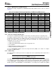
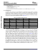
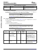
Table 3-14. Reset Types (continued)
Type Initiator Effect
Module Reset ARM software Resets a specific module. Allows the ARM to
independently reset any module. Module reset is
intended as a debug tool not as a tool to use in
production.
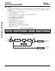
After POR, warm reset, and max reset, the chip is in its default configuration. This section highlights the
default configurations associated with PLLs, clocks, ARM boot mode, and AEMIF.
NOTE
Default configuration is the configuration immediately after POR, warm reset, and max
reset and just before the boot process begins. The boot ROM updates the configuration.
See Section 3.12 for more information on the boot process.
The device configuration pins are described in Table 3-15 . The device configuration pins are latched at
reset and allow you to configure all of the following options at reset:
• ARM Boot Mode
• Asynchronous EMIF pin configuration
These pins are described further in the following sections.
NOTE
The device configuration pins are multiplexed with AEMIF pins. After the device
configuration pins are sampled at reset, they automatically change to function as AEMIF
pins. Pin multiplexing is described in Section 3.8 .
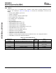
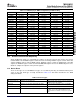
Table 3-15. Device Configuration
Default Setting (by
internal
Device Sampled pull-up/
Configuration Input Function Pin pull-down) Device Configuration Affected
BTSEL[1:0] Selects ARM boot mode EM_A[13:12] 00 If any ROM boot mode is selected, GIO61
00 = Boot from ROM (NAND) (NAND) is used to indicated boot status.
01 = Boot from AEMIF If NAND boot is selected, CE0 is used for
10 = Boot from ROM NAND. Use AECFG[3:0] to configure
(MMC/SD) AEMIF pins for NAND.
11 = Boot from ROM (UART) If AEMIF boot is selected, CE0 is used for
AEMIF device (OneNAND, ROM). Use
AECFG[3:0] to configure AEMIF pins for
NAND.
If MMC/SD boot is selected, MMC/SD0 is
used.
AECFG[3:0] Selects AEMIF pin EM_A[11:8] 1101 Selects the AEMIF pin configuration. Refer
configuration (NAND) to pin-muxing information in Section 3.9.1 .
Note that AECFG[3:0] affects both AEMIF
(BTSEL[1:0]=01) and NAND
(BTSEL[1:0]=00) boot modes.
Detailed Device Description80 Submit Documentation Feedback