
Digital Media System-on-Chip (DMSoC) Product Preview


www.ti.com
PRODUCT PREVIEW
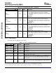
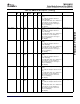
2.4.16 Emulation
TMS320DM355
Digital Media System-on-Chip (DMSoC)
SPRS463A – SEPTEMBER 2007 – REVISED SEPTEMBER 2007
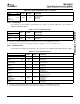
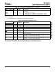
Table 2-21. System/Boot Terminal Functions (continued)
TERMINAL
TYPE
(1)
OTHER
(2) (3)
DESCRIPTION
NAME NO.
Async EMIF: Address bus bit 08
GIO: GIO[062]
EM_A08/
PD
System: AECFG[0] sets default for:
GIO062/ T19 I/O/Z
V
DD
AECFG[0] • PinMux2.EM_A0_BA1 - AEMIF address width (OneNAND, or NAND)
• PinMux2.EM_A13_3 - AEMIF address width (OneNAND, or NAND)
The emulation interface allow software and hardware debugging.
Table 2-22. Emulation Terminal Functions
TERMINAL
TYPE
(1)
OTHER
(2) (3)
DESCRIPTION
NAME NO.
TCK E10 I V
DD
JTAG test clock input
PU
TDI D9 I JTAG test data input
V
DD
TDO E9 O V
DD
JTAG test data output
PU
TMS D8 I JTAG test mode select
V
DD
PD
TRST C9 I JTAG test logic reset (active low)
V
DD
RTCK E11 O V
DD
JTAG test clock output
JTAG emulation 0 I/O
PU
EMU0 E8 I/O/Z EMU[1:0] = 00 - Force Debug Scan chain (ARM and ARM ETB TAPs connected)
V
DD
EMU[1:0] = 11 - Normal Scan chain (ICEpick only)
JTAG emulation 1 I/O
PU
EMU1 E7 I/O/Z EMU[1:0] = 00 - Force Debug Scan chain (ARM and ARM ETB TAPs connected)
V
DD
EMU[1:0] = 11 - Normal Scan chain (ICEpick only)
(1) I = Input, O = Output, Z = High impedance, S = Supply voltage, GND = Ground, A = Analog signal.
(2) Specifies the operating I/O supply voltage for each signal. See Section 5.3 , Power Supplies for more detail.
(3) PD = pull-down, PU = pull-up. (To pull up a signal to the opposite supply rail, a 1 k Ω resistor should be used.)
Submit Documentation Feedback Device Overview 35