
Digital Media System-on-Chip (DMSoC) Product Preview


www.ti.com
PRODUCT PREVIEW
5.15 Timer
5.15.1 Timer Electrical Data/Timing
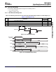
1
2
4
4
3
TIM_IN
TMS320DM355
Digital Media System-on-Chip (DMSoC)
SPRS463A – SEPTEMBER 2007 – REVISED SEPTEMBER 2007
The contains four software-programmable timers. Timer 0, Timer 1, and Timer 3 (general-purpose timers)
can be programmed in 64-bit mode, dual 32-bit unchained mode, or dual 32-bit chained mode. Timer 3
supports additional features over the other timers: external clock/event input, period reload, output event
tied to Real Time Out (RTO) module, external event capture, and timer counter register read reset. Timer
2 is used only as a watchdog timer. Timer 2 is tied to device reset.
• 64-bit count-up counter
• Timer modes:
– 64-bit general-purpose timer mode (Timer 0, 1, 3)
– Dual 32-bit general-purpose timer mode (Timer 0, 1, 3)
– Watchdog timer mode (Timer 2)
• Two possible clock sources:
– Internal clock
– External clock/event input via timer input pins (Timer 3)
• Three possible operation modes:
– One-time operation (timer runs for one period then stops)
– Continuous operation (timer automatically resets after each period)
– Continuous operation with period reload (Timer 3)
• Generates interrupts to the ARM CPU
• Generates sync event to EDMA
• Generates output event to device reset (Timer 2)
• Generates output event to Real Timer Out (RTO) module (Timer 3)
• External event capture via timer input pins (Timer 3)
For more detailed information, see the TMS320DM355 DMSoC 64-bit Timer User's Guide for more
information (SPRUEE5).
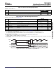
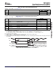
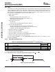
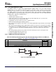
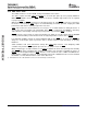
Table 5-45. Timing Requirements for Timer Input
(1) (2) (3)
(see Figure 5-46 )
DM355
NO. UNIT
MIN MAX
1 t
c(TIN)
Cycle time, TIM_IN 4P ns
2 t
w(TINPH)
Pulse duration, TIM_IN high 0.45C 0.55C ns
3 t
w(TINPL)
Pulse duration, TIM_IN low 0.45C 0.55C ns
4 t
t(TIN)
Transition time, TIM_IN 0.05C ns
(1) GPIO000, GPIO001, GPIO002, and GPIO003 can be used as external clock inputs for Timer 3. See the TMS320DM355 DMSoC 64-bit
Timer User's Guide for more information (SPRUEE5).
(2) P = MXI1/CLKIN cycle time in ns. For example, when MXI1/CLKIN frequency is 24 MHz use P = 41. 6 ns.
(3) C = TIM_IN cycle time in ns. For example, when TIM_IN frequency is 24 MHz use C = 41. 6 ns
Figure 5-46. Timer Input Timing
144 Peripheral Information and Electrical Specifications Submit Documentation Feedback