
Digital Media System-on-Chip (DMSoC) Product Preview

www.ti.com
PRODUCT PREVIEW
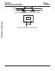
5.11 Universal Asynchronous Receiver/Transmitter (UART)
5.11.1 UART Electrical Data/Timing
TMS320DM355
Digital Media System-on-Chip (DMSoC)
SPRS463A – SEPTEMBER 2007 – REVISED SEPTEMBER 2007
The contains 3 separate UART modules (1 with hardware flow control). These modules performs
serial-to-parallel conversion on data received from a peripheral device or modem, and parallel-to-serial
conversion on data received from the CPU. Each UART also includes a programmable baud rate
generator capable of dividing the 24MHz reference clock by divisors from 1 to 65,535 to produce a 16 x
clock driving the internal logic. The UART modules support the following features:
• Frequency pre-scale values from 1 to 65,535 to generate appropriate baud rates
• 16-byte storage space for both the transmitter and receiver FIFOs
• Unique interrupts, one for each UART
• Unique EDMA events, both received and transmitted data for each UART
• 1, 4, 8, or 14 byte selectable receiver FIFO trigger level for autoflow control and DMA
• Programmable auto-rts and auto-cts for autoflow control (supported on UART2)
• Programmable serial data formats
– 5, 6, 7, or 8-bit characters
– Even, odd, or no parity bit generation and detection
– 1, 1.5, or 2 stop bit generation
• False start bit detection
• Line break generation and detection
• Internal diagnostic capabilities
– Loopback controls for communications link fault isolation
– Break, parity, overrun, and framing error simulation
• Modem control functions: CTS, RTS (supported on UART2)
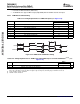
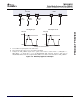
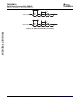
Table 5-26. Timing Requirements for UARTx Receive (see Figure 5-35 )
DM355
NO. UNIT
MIN MAX
4 t
w(URXDB)
Pulse duration, receive data bit (RXDn) 0.99U
(1)
1.05U
(1)
ns
5 t
w(URXSB)
Pulse duration, receive start bit 0.99U
(1)
1.05U
(1)
ns
(1) U = UART baud time = 1/programmed baud rate.
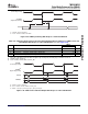
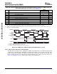
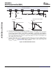
Table 5-27. Switching Characteristics Over Recommended Operating Conditions for UARTx Transmit
(see Figure 5-35 )
DM355
NO. PARAMETER UNIT
MIN MAX
UART0/1 Maximum programmable baud rate 1.5
1 f
(baud)
MHz
UART2 Maximum programmable baud rate 5
2 t
w(UTXDB)
Pulse duration, transmit data bit (TXDn) U - 2
(1)
U + 2
(1)
ns
3 t
w(UTXSB)
Pulse duration, transmit start bit U - 2
(1)
U + 2
(1)
ns
(1) U = UART baud time = 1/programmed baud rate.
Submit Documentation Feedback Peripheral Information and Electrical Specifications 129