
Digital Media System-on-Chip (DMSoC) Product Preview


www.ti.com
PRODUCT PREVIEW
PCLK
(PositiveEdgeClocking)
18
20
HD
VD
PCLK
(NegativeEdgeClocking)
5.9.2 Video Processing Back-End (VPBE)
TMS320DM355
Digital Media System-on-Chip (DMSoC)
SPRS463A – SEPTEMBER 2007 – REVISED SEPTEMBER 2007
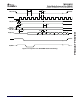
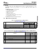
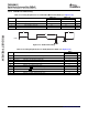
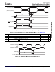
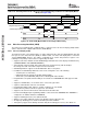
Table 5-20. Switching Characteristics Over Recommended Operating Conditions for VPFE (CCD) Master
Mode (see Figure 5-26 )
DM355
NO. PARAMETER UNIT
MIN MAX
18 t
d(PCLKL-HDIV)
Delay time, PCLK edge to HD invalid 3 11 ns
20 t
d(PCLKL-VDIV)
Delay time, PCLK edge to VD invalid 3 11 ns
Figure 5-26. VPFE (CCD) Master Mode Control Output Data Timing
The Video Processing Back-End of VPBE module is comprised of the On Screen Display (OSD) module
and the Video Encoder / Digital LCD Controller (VENC/DLCD).
5.9.2.1 On-Screen Display (OSD)
The primary function of the OSD module is to gather and blend video data and display/bitmap data and
then pass it to the Video Encoder (VENC) in YCbCr format. The video and display data is read from
external DDR2/mDDR memory. The OSD is programmed via control and parameter registers. The
following are the primary features that are supported by the OSD.
• Support for two video windows and two OSD bitmapped windows that can be displayed simultaneously
(VIDWIN0/VIDWIN1 and OSDWIN0/OSDWIN1).
• Video windows supports YCbCr data in 422 format from external memory, with the ability to
interchange the order of the CbCr component in the 32-bit word
• OSD bitmap windows support 1/2/4/8 bit width index data of color palette
• In addition one OSD bitmap window at a time can be configured to one of the following:
– YUV422 (same as video data)
– RGB format data in 16-bit mode (R=5bit, G=6bit, B=5bit)
– 24-bit mode (each R/G/B=8bit) with pixel level blending with video windows
• Programmable color palette with the ability to select between a RAM/ROM table with support for 256
colors.
• Support for 2 ROM tables, one of which can be selected at a given time
• Separate enable/disable control for each window
• Programmable width, height, and base starting coordinates for each window
• External memory address and offset registers for each window
• Support for x2 and x4 zoom in both the horizontal and vertical direction
• Pixel-level blending/transparency/blinking attributes can be defined for OSDWIN0 when OSDWIN1 is
configured as an attribute window for OSDWIN0.
• Support for blinking intervals to the attribute window
• Ability to select either field/frame mode for the windows (interlaced/progressive)
• An eight step blending process between the bitmap and video windows
• Transparency support for the bitmap and video data (when a bitmap pixel is zero, there will be no
Peripheral Information and Electrical Specifications120 Submit Documentation Feedback