
Stereo System User Manual

www.ti.com
TMS320C6727, TMS320C6726, TMS320C6722
Floating-Point Digital Signal Processors
SPRS268E – MAY 2005 – REVISED JANUARY 2007
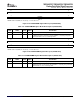
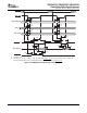
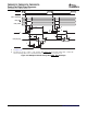
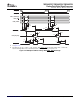
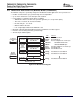
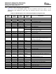
Table 4-16. UHPI Read and Write Switching Characteristics
(1) (2)
NO. PARAMETER MIN MAX UNIT
Case 1. HPIC or HPIA read 1 15
Case 2. HPID read with no
9 * 2H + 20
(3)
auto-increment
Case 3. HPID read with
1 t
d(DSL-HDV)
Delay time, DS low to HD valid ns
auto-increment and read FIFO 9 * 2H + 20
(3)
initially empty
Case 4. HPID read with
auto-increment and data previously 1 15
prefetched into the read FIFO
2 t
dis(DSH-HDV)
Disable time, HD high-impedance from DS high 1 4 ns
3 t
en(DSL-HDD)
Enable time, HD driven from DS low 3 15 ns
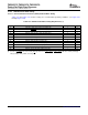
4 t
d(DSL-HRDYH)
Delay time, DS low to UHPI_HRDY high 12 ns
5 t
d(DSH-HRDYH)
Delay time, DS high to UHPI_HRDY high 12 ns
Case 1. HPID read with no
10 * 2H + 20
(3)
auto-increment
Delay time, DS low to UHPI_HRDY
6 t
d(DSL-HRDYL)
ns
Case 2. HPID read with
low
auto-increment and read FIFO 10 * 2H + 20
(3)
initialy empty
7 t
d(HDV-HRDYL)
Delay time, HD valid to UHPI_HRDY low 0 ns
Case 1. HPIA write 5 * 2H + 20
(3)
Delay time, DS high to
Case 2. HPID read with
34 t
d(DSH-HRDYL)
ns
UHPI_HRDY low
auto-increment and read FIFO 5 * 2H + 20
(3)
initially empty
Delay time, DS low to UHPI_HRDY low for HPIA write and FIFO not
35 t
d(DSL-HRDYL)
40 * 2H + 20
(3)
ns
empty
36 t
d(HASL-HRDYH)
Delay time, UHPI_HAS low to UHPI_HRDY high 12 ns
(1) H = 0.5 * SYSCLK2 period
(2) DS refers to HSTROBE. HAD refers to UHPI_HCNTL[0], UHPI_HCNTL[1], UHPI_HHWIL, and UHPI_HR W.
(3) Max delay is a best case, assuming no delays due to resource conflicts between UHPI and dMAX or CPU. UHPI_HRDY should always
be used to indicate when an access is complete instead of relying on these parameters.
Submit Documentation Feedback Peripheral and Electrical Specifications 63