
Stereo System User Manual

www.ti.com
2.6 High-Performance Crossbar Switch
SYSCLK3
SYSCLK1 SYSCLK2
SYSCLK3
BR3 BR4
2 1
Priority
EMIF
External
Memory
SDRAM/
Flash
Priority
21 3 4
T2
SYSCLK2
SYSCLK1
BR1
SYSCLK2
SYSCLK1
BR2
Program
Master
Port
(PMP)
CPU
Slave
Port
(CSP)
Data
Master
Port
(DMP)
Memory Controller
M1 T1 M2
Priority
1 2 3
PLL SPI0 I2C0 I2C1RTI SPI1
Peripheral Configuration Bus
McASP2McASP1McASP0
McASP DMA Bus
Priority
1 2 3
Priority
1 2
T4
T3
dMAX MAX0 Unit Master Port − High Priority
dMAX MAX1 Unit Master Port − Second Priority
Memory Controller DMP − Data Read/Write by CPU
UHPI Master Interface (External Host CPU)
UHPI
Universal Host-Port
Interface
M5
MAX0 MAX1
1 2 3
Priority
Config
dMAX
T5M3 M4
External
Host MCU
Config
ROM RAM CPU
Program
Cache
Crossbar
TMS320C6727, TMS320C6726, TMS320C6722
Floating-Point Digital Signal Processors
SPRS268E – MAY 2005 – REVISED JANUARY 2007
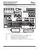
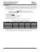
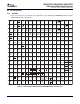
The C672x DSP includes a high-performance crossbar switch that acts as a central hub between bus
masters and targets. Figure 2-4 illustrates the connectivity of the crossbar switch.
Figure 2-4. Block Diagram of Crossbar Switch
As shown in Figure 2-4 , there are five bus masters:
M1 Memory controller DMP for CPU data accesses to peripherals and EMIF.
M2 Memory controller PMP for program cache fills from the EMIF.
M3 dMAX HiMAX master port for high-priority DMA accesses.
M4 dMAX LoMAX master port for lower-priority DMA accesses.
M5 UHPI master port for an external MCU to access on-chip and off-chip memories.
Device Overview12 Submit Documentation Feedback