
Interpolated Control (VIC) Port Reference Guide

Video Input Filtering
Video Capture Port3-26 SPRU629
VCTL2 is a VSYNC (vertical sync) input, then a long field is always detected.
(Even if VCYSTOPn is set to the last active line, VCOUNT usually increments
past VCYSTOPn + 1 while it counts the vertical front porch lines that occur
prior to VSYNC active.)
3.5 Video Input Filtering
The video input filter performs simple hardware scaling and resampling on
incoming 8-bit BT.656 or 8-bit Y/C data. Filtering hardware is always disabled
during 10-bit or raw data capture modes. For proper filter operation, the
channel’s EXC bit in VCxCTL must be cleared to 0 (embedded timing refer-
ence codes used) and the CAPEN input must not go inactive during the active
video window.
3.5.1 Input Filter Modes
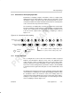
The input filter has four modes of operation: no-filtering, ½ scaling, chrominance
resampling, and ½ scaling with chrominance resampling. Filter operation is
determined by the CMODE, SCALE, and RESMPL bits of VCxCTL.
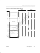
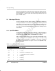
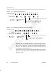
Table 3–10 shows the input filter mode selection. When 8-bit BT.656 or Y/C
capture operation is selected (CMODE = x00), scaling is selected by setting
the SCALE bit and chrominance resampling is selected by setting the
RESMPL bit. If 8-bit BT.656 or Y/C capture is not selected (CMODE ≠ x00),
filtering is disabled.
Table 3–10. Input Filter Mode Selection
VCxCTL Bit
CMODE RESMPL SCALE Filter Operation
x00
0 0 No filtering
x00 0 1 ½ scaling
x00 1 0 Chrominance resampling (full scale)
x00 1 1 ½ scaling with chrominance resampling
x01 x x No filtering
x10 x x No filtering
x11
x x No filtering